
Device for stripping injection of heavy ion synchrotron

A synchrotron, heavy ion technology, applied in magnetic resonance accelerators, accelerators, electrical components, etc., can solve the problems of increasing the operating cost of the accelerator, damaging the carbon film by motion, affecting the operating efficiency of the accelerator, etc., to improve the operating efficiency and reduce the impact. , the effect of reducing operating costs

Pending Publication Date: 2021-07-23
INST OF MODERN PHYSICS CHINESE ACADEMY OF SCI
View PDF11 Cites 7 Cited by
  • Summary
  • Abstract
  • Description
  • Claims
  • Application Information

AI Technical Summary

Problems solved by technology

[0004] In the case that the above-mentioned stripping implantation location is very limited and the vacuum of the accelerator is ultra-high vacuum, the existing device for heavy ion synchrotron stripping implantation requires the accelerator to be shut down, vacuum broken, and vacuum pumped again every time the carbon film is replaced. , and to send the stripped carbon film from the initial position to the injection stripping point, the span of 1200mm is required, and the effective gap of the film holder is only 2-3mm. The deformation and unstable movement of the target rod will cause the target head to touch the pipe wall and damage the carbon film. film, which seriously affects the operating efficiency of the accelerator and greatly increases the operating cost of the accelerator

Method used


Image

  • Device for stripping injection of heavy ion synchrotron
  • Device for stripping injection of heavy ion synchrotron
  • Device for stripping injection of heavy ion synchrotron

Examples


Embodiment Construction

[0045] In order to make the purpose, technical solution and advantages of the present invention clearer, the technical solution of the present invention will be clearly and completely described below in conjunction with the accompanying drawings. Apparently, the described embodiments are some, but not all, embodiments of the present invention. Based on the embodiments of the present invention, all other embodiments obtained by persons of ordinary skill in the art without making creative efforts belong to the protection scope of the present invention.

[0046] In the description of the present invention, it should be noted that the orientation or positional relationship indicated by the terms "upper", "lower", "front", "rear", "inner", "outer", "horizontal", "vertical" etc. Based on the orientation or positional relationship shown in the drawings, it is only for the convenience of describing the present invention and simplifying the description, rather than indicating or implyi...


PUM


Abstract

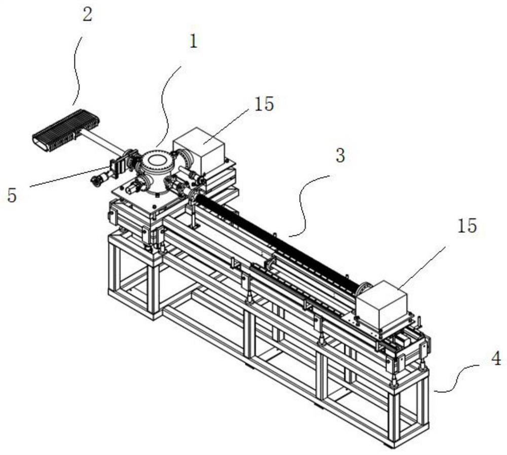
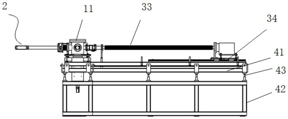
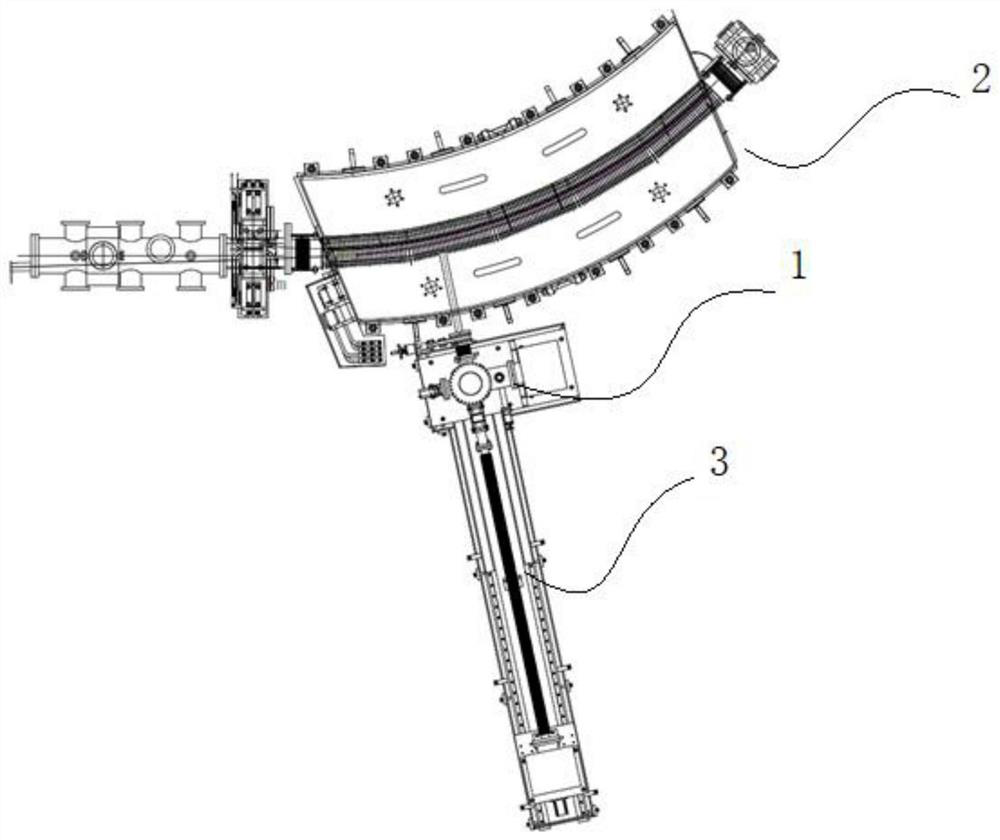
The invention discloses a device for stripping injection of a heavy ion synchrotron. The device comprises a stripping film storage chamber, a stripping injection chamber and a stripping film conveying mechanism; the stripping film storage chamber comprises a vacuum storage chamber, a film frame rotating disc, a film frame and a first driving mechanism, and the film frame rotating disc is arranged in the vacuum storage chamber; a plurality of film frames are uniformly distributed on the film frame rotating disc along the circumferential direction; the first driving mechanism is configured to drive the film frame rotating disc to transfer between an initial position and a film changing position in the vacuum storage chamber; the stripping injection chamber is connected with the vacuum storage chamber, and a stripping injection point is appointed in the stripping injection chamber; the stripping film conveying mechanism comprises a film frame grabbing assembly, a transmission rod, a vacuum corrugated pipe assembly and a second driving mechanism; and the far end of the vacuum corrugated pipe assembly is connected to the vacuum storage cavity, the transmission rod is arranged in the vacuum corrugated pipe assembly in a penetrating mode, the far end of the transmission rod is provided with the membrane frame grabbing assembly, and the near end of the transmission rod and the near end of the vacuum corrugated pipe assembly are jointly connected with the second driving mechanism.

Description

technical field [0001] The invention relates to a device for stripping and implanting a heavy ion synchrotron, belonging to the technical field of accelerators. Background technique [0002] At present, the injection methods of synchrotron mainly include multi-turn injection, multiple multi-turn injection with the aid of cooling effect, stripping injection, etc. The injection gain of multi-turn injection is generally only about 15 times due to the limitation of Liu Wei's theorem; Sub-multi-turn can achieve greater beam gain, but requires phase space cooling devices, such as electronic cooling, random cooling, etc. This cooling device is technically difficult and expensive, and is not suitable for use in medical heavy ion devices; and Stripping injection is a method of beam injection by hitting the beam on the stripping film, causing the loss of extranuclear electrons in the beam, thereby changing the trajectory of the beam. Lift-off implantation can easily achieve an implan...

Claims


Application Information

Patent Timeline
Patent Type & Authority Applications(China)
IPC IPC(8): H05H13/04H05H7/08
CPCH05H13/04H05H7/08
Inventor 康新才毛瑞士肖国青原有进李维龙赵铁成李敏马维年
Owner INST OF MODERN PHYSICS CHINESE ACADEMY OF SCI
Learn More