Check patentability & draft patents in minutes with Patsnap Eureka AI!

3D printed structure

A 3D printing and structural layer technology, applied in the field of 3D printing structures, can solve problems such as inflexibility, reduced flexibility, and increased material weight

Pending Publication Date: 2021-07-23
ECCO SKO
View PDF7 Cites 0 Cited by
  • Summary
  • Abstract
  • Description
  • Claims
  • Application Information

AI Technical Summary

Problems solved by technology

[0002] A common problem with 3D printed structures is that structures of this kind are usually made from relatively stiff materials, which means that the structure of the 3D printed structure can be relatively inflexible due to the composition of the materials used for printing
One problem with such flexible layers is that while increasing the structural strength of the material, the flexibility of the layer decreases, here this also increases the weight of the material

Method used


Image

  • 3D printed structure
  • 3D printed structure
  • 3D printed structure

Examples


Embodiment Construction

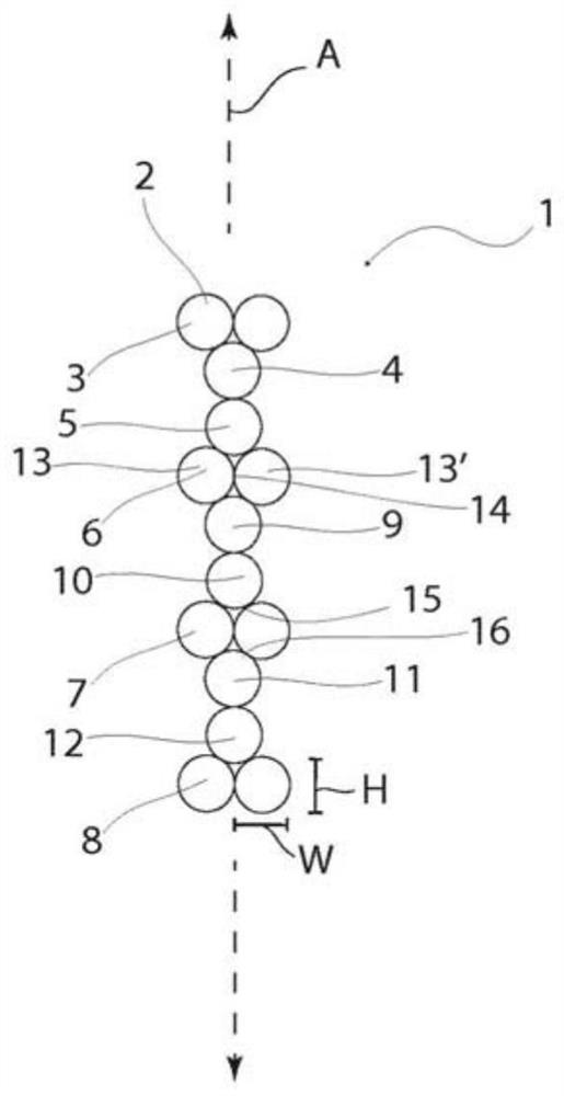
[0098] Fig. 1 shows a first exemplary embodiment of a 3D printed structure 1 with a first wall 2 having a plurality of layers extending along a first axis A, seen in a schematic cross-sectional view. The first wall 2 comprises a first secondary structural layer 3 , a first flexible layer 4 and a second flexible layer 5 . In this exemplary embodiment, the first wall 2 includes a second level structure layer 6, a third level structure layer 7 and a fourth level structure layer 8, wherein the second level structure layer 6 and the tertiary structure layer 7, and each of the tertiary structural layer 7 and the fourth secondary structural layer 8 is separated by two flexible layers 9, 10, 11, 12 respectively. That is, the structure in which the first secondary structural layer 3 and the first 3 and second pliable layers 4 is repeated in the longitudinal direction A of the wall 2 along the length of the wall 2 .

[0099] The primary structure wall 3 and the first flexible wall 4, t...


PUM


Abstract

A 3D printed structure of an elastic material, the 3D printed structure comprising: at least a first wall having a plurality of layers extending along a first axis, the first wall comprising at least a primary structural layer and a first flexible layer and a second flexible layer, where the primary structural layer has a first rigidity and the first flexible and / or the second flexible layer has a second rigidity, wherein the first rigidity is larger than the second rigidity.

Description

technical field [0001] A 3D printed structure of an elastic material, the 3D printed structure comprising: at least a first wall having a plurality of layers extending along a first axis, the first wall comprising at least a primary structural layer, a first pliable layer, and A second flexible layer. Background technique [0002] A common problem with 3D printed structures is that structures of this kind are often made of relatively stiff materials, which means that the structure of 3D printed structures may be relatively inflexible due to the composition of the materials used for printing. [0003] CN 105034361 discloses a honeycomb core containing cells of different thicknesses and shapes, and at least part of the wall thickness of the obtained honeycomb unit is at least part of the wall thickness along the center of the honeycomb unit towards the two sides of the honeycomb unit The direction of the ends is gradually increased so that a honeycomb clamp can be added. The...

Claims


Application Information

Patent Timeline
IPC IPC(8): A43B13/18B33Y80/00B29D99/00A43B13/14B29D35/12A43B13/04A43B13/12
CPCA43B13/14A43B13/181B33Y80/00B29D99/0089A43B13/125A43B13/187A43B13/04B29D35/122B29D35/142B29C64/106B29C64/336B33Y10/00B33Y70/00B29K2105/046B29L2031/751B29L2031/608B29L2031/58B29K2083/00B29L2031/504B29C64/118
Inventor J·米切尔P·卡卢奇
Owner ECCO SKO
Features
  • R&D
  • Intellectual Property
  • Life Sciences
  • Materials
  • Tech Scout
  • Unparalleled Data Quality
  • Higher Quality Content
  • 60% Fewer Hallucinations
Learn More