Damping valve for vibration damper

A vibration damper and damping valve technology, applied in the field of damping valves, can solve the problems of small elasticity and fatigue strength of elastomer components

Active Publication Date: 2021-07-23
ZF FIEDRICHSHAFEN AG
View PDF11 Cites 0 Cited by
  • Summary
  • Abstract
  • Description
  • Claims
  • Application Information

AI Technical Summary

Problems solved by technology

[0003] The fundamental problem with elastomeric elements in such applications is that they generally have too little elasticity due to too high a Shore hardness
Fatigue strength issues may arise at the lower Shore hardness associated with this design

Method used


Image

  • Damping valve for vibration damper
  • Damping valve for vibration damper
  • Damping valve for vibration damper

Examples


Embodiment Construction

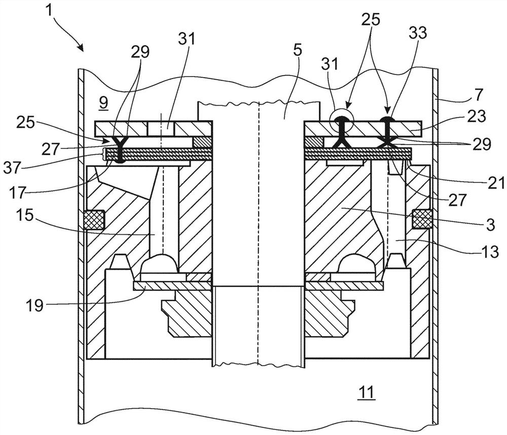
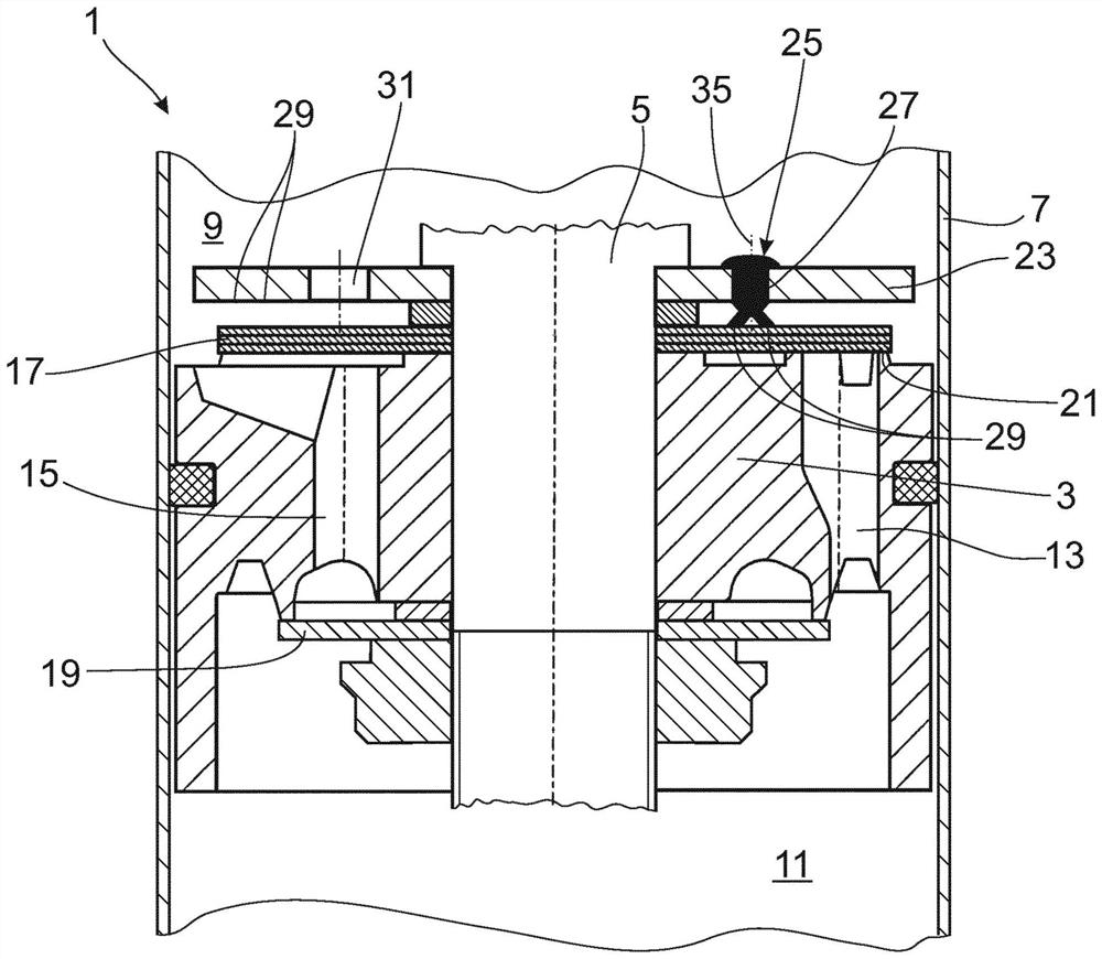
[0026] figure 1 A damping valve 1 for a vibration damper of any desired design is shown. The damping valve 1 comprises a damping valve body 3 which is fixed on a piston rod 5 . The invention is not limited to this embodiment and can be used, for example, in foot valves or also in the area of ​​adjustable damping valves.

[0027] The damping valve body 3 divides the cylinder body 7 of the vibration damper into a working chamber on the side of the piston rod and a working chamber 9; 11 away from the piston rod, both of which are filled with damping medium. In the damping valve body 3 , the through-channels 13 ; 15 for the respective flow directions are embodied in different subcircuits. The configuration of the through-channel is to be regarded as exemplary only. The outlet side of the through-channel 13 ; 15 is at least partially covered by at least one valve disk 17 ; 19 .

[0028] When the flow starts from the working chamber 11 facing away from the piston rod to the valv...


PUM


Abstract

The invention relates to a damping valve for a vibration damper, comprising a damping valve body having at least one through channel, the outlet opening of which is covered by at least one valve disk, wherein the valve disk is prestressed in the closing direction by at least one elastomer element which is supported on a support disk, wherein the elastomer element has a nodal web, from which extend at least two spring webs in an oblique manner.

Description

technical field [0001] The invention relates to a damping valve for a vibration damper according to the preamble of patent claim 1 . Background technique [0002] DE 10 2016 218 375 describes a damping valve in which a valve disk performs a lifting movement against the ejection force of an elastomer element or elements. For example, in the embodiment according to FIG. 9 , the elastomer element has a circular cross section with extrusion chambers. The extrusion chamber is filled with a damping medium and has radial outflow openings. [0003] A fundamental problem with elastomeric elements in such applications is that the elastomeric elements generally have too little elasticity due to too high a Shore hardness. Fatigue strength issues may arise at the lower Shore hardness associated with this design. [0004] Usually a plurality of valve disks or also spring disks (also including star springs) are arranged in a disk pack in the damping valve. For better assembly, it is kn...

Claims


Application Information

Patent Timeline
Patent Type & Authority Applications(China)
IPC IPC(8): F16F9/348
CPCF16F9/3487
Inventor K·施密茨A·克内泽维奇J·罗塞勒
Owner ZF FIEDRICHSHAFEN AG
Why Eureka
Try Eureka