Novel clinical puncture equipment for department of cardiology

A new type of cardiology technology, applied in the field of new clinical puncture equipment in the cardiology department, can solve the problems of secondary injury of patients, reduce the accuracy of test results, and pull the puncture needle away from the human body, etc., and achieve the effect of simple operation

Pending Publication Date: 2021-07-27
南通市传染病防治院
View PDF0 Cites 0 Cited by
  • Summary
  • Abstract
  • Description
  • Claims
  • Application Information

AI Technical Summary

Problems solved by technology

[0004] In the prior art, the outside of the perforation is often positioned by setting a pressing device on the outside of the puncture needle, but during the retraction process of the puncture needle, due to an outward pulling force, the displacement of the pressing device will be forced, resulting in the failure of the puncture needle. The exiting part cannot continue to pull away from the human body along the original perforation or even expand the perforation, causing secondary injury to the patient and reducing the accuracy of the test results; in addition, after the puncture is completed, the formed perforation still needs to stop bleeding. In the technology, the puncture device needs to be removed, and then another hemostatic cotton is used to stop the bleeding. The operation is more troublesome, and it is not the first time to stop the bleeding, and the hemostatic effect is not good.

Method used


Image

  • Novel clinical puncture equipment for department of cardiology
  • Novel clinical puncture equipment for department of cardiology
  • Novel clinical puncture equipment for department of cardiology

Examples


Embodiment 1

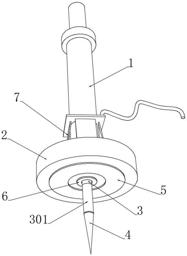
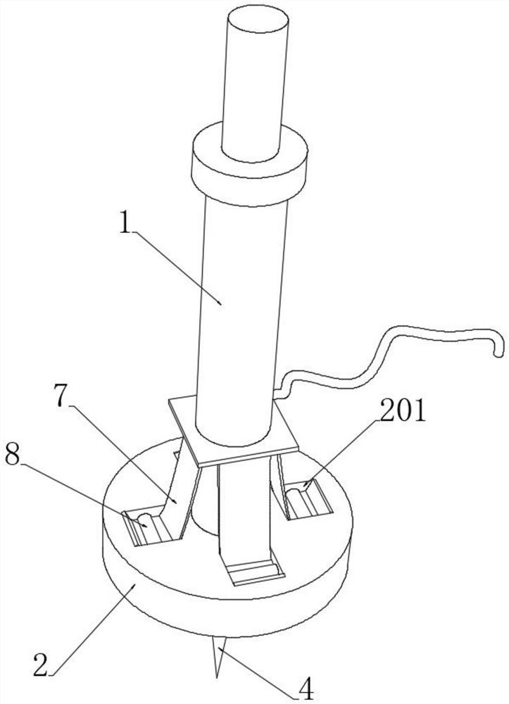
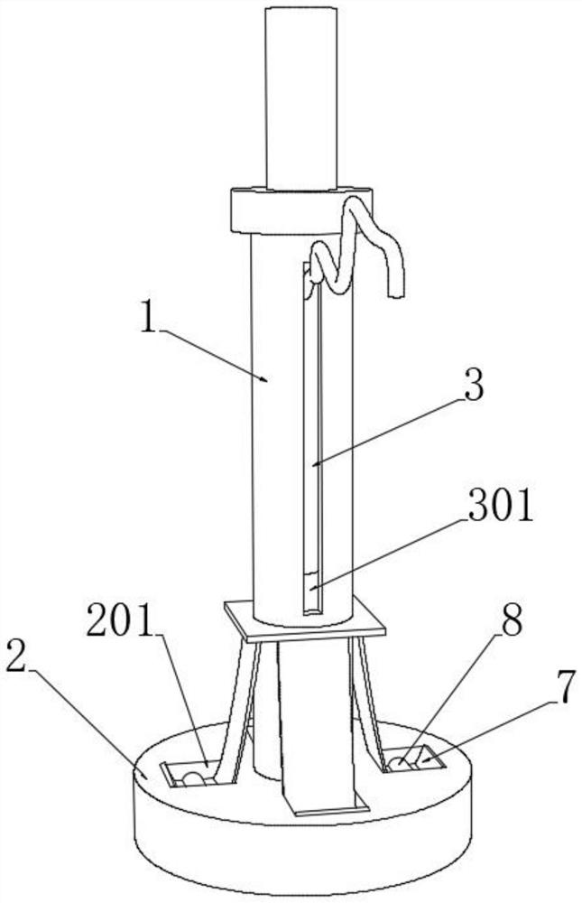
[0041] see Figure 1-4 , a new clinical puncture device for cardiology, comprising a magnetic isolation sleeve 1, a needle tube 3 with a puncture needle 4 at the bottom provided inside the magnetic isolation sleeve 1, a pressing pad 2 connected to the bottom end of the magnetic isolation sleeve 1, The bottom end of the pressing pad 2 is provided with an extrusion cavity and a communication cavity, and an extrusion ring 5 is embedded inside the extrusion cavity. The end close to the top is connected with the inner wall of the magnetic isolation sleeve 1 through a movable sleeve, the top side wall of the needle tube 3 is connected with a suction tube, and the outer wall of the magnetic isolation sleeve 1 is provided with an active cavity corresponding to the position of the suction tube , when in use, the suction tube is connected to the external suction device, which is beneficial to the suction pump, and the technician holds the pushing head to puncture, so that the puncture n...


PUM


Abstract

The invention discloses novel clinical puncture equipment for the department of cardiology, and belongs to the technical field of medical equipment. A plurality of magnetic extrusion pads are distributed at the top end of a pressing pad, in the puncture process, a magnetic ring penetrates through a magnetic isolation sleeve and then is close to the magnetic extrusion pads, and the magnetic extrusion pads are affected by magnetic attraction and extrude the bottom end of the pressing pad; an extrusion ring sleeve can further press the skin near a perforated hole in the puncture process, a needle tube and a puncture needle are not prone to shifting in the puncture process to cause trauma to the perforated hole position, meanwhile, a hemostatic ring sleeve is arranged on the inner side of the extrusion ring sleeve, a pair of magnetic hemostatic bodies is arranged at the inner bottom of the hemostatic ring sleeve, the magnetic hemostatic bodies and the magnetic ring are arranged in a repulsive mode, when the magnetic ring is close to the magnetic hemostatic bodies, the pair of magnetic hemostatic bodies oppositely move and retreat into a containing cavity, perforating of the puncture needle is facilitated, and after perforating work is completed, the magnetic ring is far away from the magnetic hemostatic bodies, the pair of magnetic hemostatic bodies oppositely reset, and the magnetic hemostatic bodies match the hemostatic ring sleeve to achieve the hemostatic effect on the perforated hole.

Description

technical field [0001] The invention relates to the technical field of medical equipment, and more specifically, relates to a new type of clinical puncture equipment in the Department of Cardiology. Background technique [0002] Puncture is a term used in medical operations. It is a diagnosis and treatment technique in which a puncture needle is inserted into a body cavity to extract secretions for testing, inject gas or contrast agent into the body cavity for contrast examination, or inject drugs into the body cavity. Diagnosis and treatment technology in which the needle is directly inserted into the pericardial cavity. Patients with pericardial puncture can understand the nature of pericardial effusion by testing the fluid in the pericardial cavity, and find out the cause of pericarditis according to the nature of pericardial effusion. [0003] When the existing clinical new puncture equipment in the Department of Cardiology is pulled out of the patient's body from the pe...

Claims


Application Information

Patent Timeline
Patent Type & Authority Applications(China)
IPC IPC(8): A61B17/34A61B17/12
CPCA61B17/12A61B17/3403A61B2017/12004A61B2017/3454
Inventor 王颖周元
Owner 南通市传染病防治院
Why Eureka
Try Eureka