Truss type replaceable energy dissipation coupling beam with buckling restrained braces

A technology of buckling restraint and connecting beams, which is applied in the direction of truss beams, truss structures, joists, etc., can solve the problems of insufficient energy dissipation capacity, no replacement of energy dissipation dampers, and difficult repairs, etc., to achieve convenient processing and improve earthquake resistance Properties, the effect of convenient maintenance and replacement

Pending Publication Date: 2021-07-27
SICHUAN UNIV
View PDF12 Cites 1 Cited by
  • Summary
  • Abstract
  • Description
  • Claims
  • Application Information

AI Technical Summary

Problems solved by technology

[0005] In order to solve the problems of insufficient energy dissipation capacity of traditional coupling beams, the difficulty of repair and replacement after earthquakes, and the fact that the energy dissipation dampers

Method used


Image

  • Truss type replaceable energy dissipation coupling beam with buckling restrained braces
  • Truss type replaceable energy dissipation coupling beam with buckling restrained braces
  • Truss type replaceable energy dissipation coupling beam with buckling restrained braces

Examples


Embodiment 1

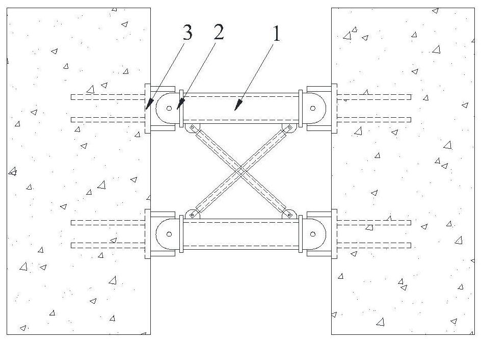
[0054] Such as Figure 1-13 Shown: A truss-type replaceable energy-dissipating connecting beam with buckling restraint bracing, including truss-type connecting beam 1, connecting beam end member 2 and embedded connecting steel plate 3:

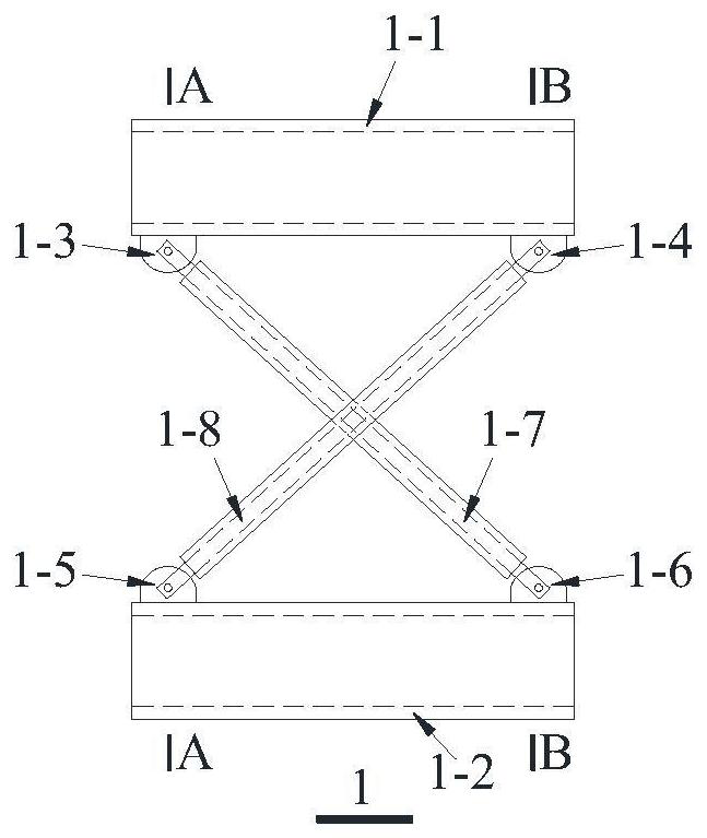
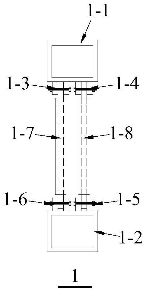
[0055] The truss-type connecting beam 1 includes a square steel pipe upper chord 1-1, a square steel pipe lower chord 1-2, a hinged connector A1-3, a hinged connector B1-4, a hinged connector C1-5, and a hinged connector D1- 6. Buckling restraint support A1-7, buckling restraint support B1-8; square steel pipe upper chord 1-1 and square steel pipe lower chord 1-2 are respectively used as the upper chord and lower chord of truss-type connecting beam 1, and hinged connection A1- 3. The hinged connectors B1-4 are respectively fixed on the two ends of the lower surface of the upper chord 1-1 of the square steel pipe, and the hinged connector 1-5C and the hinged connector D1-6 are respectively fixed on the lower chord 1-2 of the square steel pipe. ...

Embodiment 2

[0065] Such as Figures 14 to 16Shown: this embodiment is the same as the rest of embodiment 1, the difference is that the square steel pipe upper chord 1-1 and the square steel pipe lower chord 1-2 in the truss type connecting beam 1 are not hollow square steel pipes, but Concrete steel tubes are used.


PUM


Abstract

The invention discloses a truss type replaceable energy dissipation coupling beam with buckling restrained braces. The truss type replaceable energy dissipation coupling beam comprises a truss type coupling beam body, coupling beam end components and a pre-embedded connecting steel plate; the truss type coupling beam body comprises a square steel tube upper chord member, a square steel tube lower chord member, hinged connecting pieces and the buckling restrained braces; the hinge connecting pieces are fixedly connected to the two ends of the square steel tube upper chord and the square steel tube lower chord, and the two buckling restrained braces are connected with the hinge connecting pieces through pins, so that the two buckling restrained braces form diagonal web members in the truss type coupling beam, are in a cross shape and are not in contact; and the pre-embedded connecting steel plate is arranged in a wall body, the coupling beam end components are welded at the two ends of the square steel tube upper chord member and the square steel tube lower chord member, and the truss type coupling beam body and the pre-embedded connecting steel plate can be hinged through the coupling beam end components. According to the truss type replaceable energy dissipation coupling beam, shear deformation of a common coupling beam is converted into axial deformation of the buckling restrained braces, so that the buckling restrained braces serve as a first anti-seismic defensive line, and after the buckling restrained braces are damaged, the square steel tube upper chord and the square steel tube lower chord form a new coupling beam serving as a second defensive line.

Description

technical field [0001] The invention belongs to the field of civil engineering, and relates to a truss-type replaceable energy-dissipating connecting beam with buckling-constrained supports for reducing the seismic response of engineering structures. Background technique [0002] In recent years, natural disasters such as earthquakes, typhoons, and tsunamis have occurred frequently around the world, causing huge damage to cities and their buildings, and also produced a series of secondary disasters, causing huge economic losses and casualties. Among them, earthquake disaster is one of the more serious disasters. During an earthquake, the building structure system will be subjected to horizontal and vertical earthquakes. Under horizontal earthquakes, the structure will be subjected to reciprocating loads, and its lateral force-resistant components will undergo lateral deformation. , Structures that have not been properly designed will cause serious damage or even collapse und...

Claims


Application Information

Patent Timeline
IPC IPC(8): E04B1/98E04H9/02E04C3/04
CPCE04B1/98E04H9/02E04H9/021E04H9/024E04C3/04E04C2003/0404
Inventor 刘烨卢宇杰王维扬吕清芳
Owner SICHUAN UNIV
Why Eureka
Try Eureka