Indoor decoration partition wall

An interior decoration and partition wall technology, which is applied to walls, building components, and other seating furniture, etc., can solve the problems of single function and low space utilization, and achieve increased use functions, improved space utilization, and convenient operation. Effect

Inactive Publication Date: 2021-07-27
浙江安防职业技术学院
View PDF0 Cites 1 Cited by
  • Summary
  • Abstract
  • Description
  • Claims
  • Application Information

AI Technical Summary

Problems solved by technology

[0004] In view of the above-mentioned related technologies, the inventor believes that the construction of the partition wall will inevitably occupy a certain amount of indoor space, and the above-mentioned partition wall can only play an ordinary partition role, with single function and low space utilization rate

Method used


Image

  • Indoor decoration partition wall
  • Indoor decoration partition wall
  • Indoor decoration partition wall

Examples


Embodiment 1

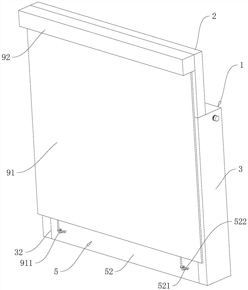
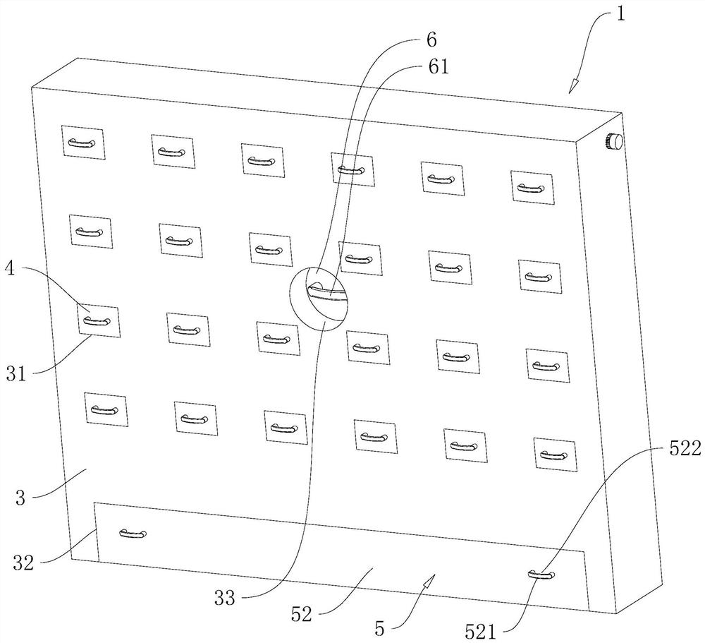
[0046] refer to figure 1 and figure 2 , a partition wall for interior decoration, comprising a wall body 1 and a transparent glass wall 2, the wall body 1 includes a frame body 3, a drawer 4 and a slide drawer 5, and the frame body 3 is provided with a drawer groove 31 for the drawer 4 to be installed and a slide for the drawer The sliding drawer groove 32 that drawer 5 is installed.

[0047] refer to figure 2 , only one drawer slot 32 is opened at the bottom of the frame body 3, and the lower side wall of the drawer slot 32 runs through, there are several drawer slots 31, and several drawer slots 31 are opened above the upper slide slot 32 of the frame body 3 and arrayed Distribution, there are several drawers 4, and several drawers 4 are slided and arranged in several drawer grooves 31 one by one, and various objects can be accommodated in the drawers 4, making full use of the space.

[0048] refer to figure 2 , the frame body 3 is also provided with a light groove 33...

Embodiment 2

[0060] refer to Figure 8 The difference between this embodiment and Embodiment 1 is that no storage space 34 is provided in the frame body 3 and the pulling assembly is no longer installed, and the backing plate 8 is stored in the placement space 54, and the backing plate 8 is only composed of several board bodies 81. The head and tail of several boards 81 are sequentially connected by rotation and folded and placed in the installation space 54. The side of the board 81 at the bottom away from the panel 52 is rotatably connected with the bottom of the drawer groove 32, and the board 81 at the bottom is close to the panel 52. One side of one side is rotatably connected with next plate body 81.

[0061] refer to Figure 9 and Figure 10 , the two side walls of the plate body 81 in the length direction at the top are integrally provided with a slide block 811 near the side of the panel 52, and the opposite side wall of the inner side plate 53 of the placement space 54 is provi...

Embodiment 3

[0063] refer to Figure 11 The difference between this embodiment and Embodiment 2 is that the bottom plate 51 of the slide drawer 5 abuts against the ground in the room, and a flexible laying mat 93 is accommodated in the slide drawer 5, and the flexible laying mat 93 can be cloth or a flexible laying mat. One side of the flexible laying mat 93 is fixed to the side of the bottom plate 51 away from the panel 52, and the other side of the flexible laying mat 93 is fixed to the bottom of the inner wall of the slider 5 with the slider groove 32, and the flexible laying mat 93 is in the shape of "S". The shape is accommodated in the slide drawer 5, and can be expanded when the slide drawer 5 is drawn out.


PUM


Abstract

The invention relates to an indoor decoration partition wall, and belongs to the technical field of indoor decoration. The indoor decoration partition wall comprises a wall body, the wall body comprises a frame body, a plurality of drawers and sliding drawers, a plurality of drawer grooves and sliding drawer grooves are formed in the frame body, the sliding drawer grooves are formed in the bottom of the frame body, the multiple drawers are slidably installed in the drawer grooves in a one-to-one correspondence mode, and the sliding drawers are slidably installed in the sliding drawer grooves. The method has the effect of improving the utilization rate of partition.

Description

technical field [0001] The present application relates to the field of interior decoration, in particular to an interior decoration partition wall. Background technique [0002] Partition walls are also called high partitions, high partitions, high partition walls, and some even call them office screens, which are mainly used in office spaces. The partition is an indispensable design element for dividing the space. Its main function is to separate the space, add shelter and layers to the space, but it does not completely separate the living room like the whole wall, but it is separated continuously. Therefore, many people in the home Space needs to be partitioned. [0003] The existing partition wall includes a wall, and the wall includes a main frame and a fireproof layer, a support layer, and a decorative layer arranged on the main frame from the inside to the outside; the fireproof layer is filled in the main frame, and the support layer is covered on the main frame. On...

Claims


Application Information

Patent Timeline
Patent Type & Authority Applications(China)
IPC IPC(8): E04B2/74A47B67/04A47B88/40A47B88/90A47C17/86
CPCA47B67/04A47C17/86A47B88/40A47B88/90E04B2/74E04B2002/7483
Inventor 朱林娜杨成磊赵欢叶豪叶璇
Owner 浙江安防职业技术学院
Why Eureka
Try Eureka