

Micro-nano drag reduction structure for high-altitude and high-speed environment
An environmental and micro-nano technology, applied in the direction of drag reduction, affecting the air flow passing through the surface of the aircraft, aircraft parts, etc., can solve the problems of complex structure and poor drag reduction effect of the drag reduction device, achieve simple structure and reduce frictional resistance , the effect of increasing the density
- Summary
- Abstract
- Description
- Claims
- Application Information
AI Technical Summary
Problems solved by technology
Method used
Image

Examples
Embodiment Construction
[0022] The present invention will be described in detail below in conjunction with specific embodiments. The following examples will help those skilled in the art to further understand the present invention, but do not limit the present invention in any form. It should be noted that those skilled in the art can make several changes and improvements without departing from the concept of the present invention. These all belong to the protection scope of the present invention.
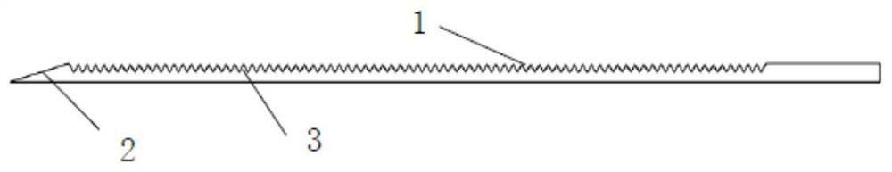
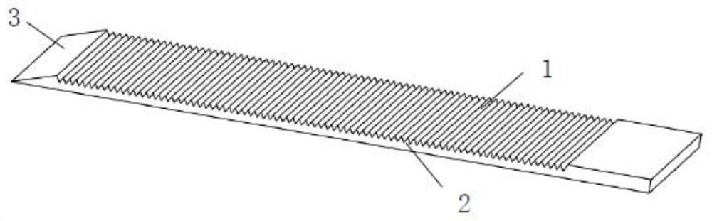
[0023] like figure 1 As shown, a micro-nano drag reduction structure for high-altitude and high-speed environments provided by the present invention includes grooves 1 etched on the outer surface of the aircraft by laser micro-nano manufacturing technology, and also includes guides integrally formed on the outer surface of the aircraft. The wind slope 2, and the wind guide slope 2 is located on the wind inlet side of the groove 1. The flight altitude of the aircraft is higher than 50 kilometers, and th...
PUM
| Property | Measurement | Unit |
|---|---|---|
| Length | aaaaa | aaaaa |
Abstract
Description
Claims
Application Information