Motor, wet type brake and wet type clutch

A technology for motors and casings, which is applied in the direction of mechanically driven clutches, brakes, clutches, etc., can solve problems such as increased viscous resistance and decreased motor efficiency, and achieve the effect of reducing viscous resistance

Active Publication Date: 2015-03-18
SUMITOMO HEAVY IND LTD
View PDF12 Cites 2 Cited by
  • Summary
  • Abstract
  • Description
  • Claims
  • Application Information

AI Technical Summary

Problems solved by technology

[0005] If the gap between the casing and the rotor end surface is reduced for axial compactness, then the motor encapsulated with coolant has the problem that the viscous resistance on the gap increases when the rotor rotates, resulting in a decrease in motor efficiency.

Method used


Image

  • Motor, wet type brake and wet type clutch
  • Motor, wet type brake and wet type clutch
  • Motor, wet type brake and wet type clutch

Examples


Embodiment Construction

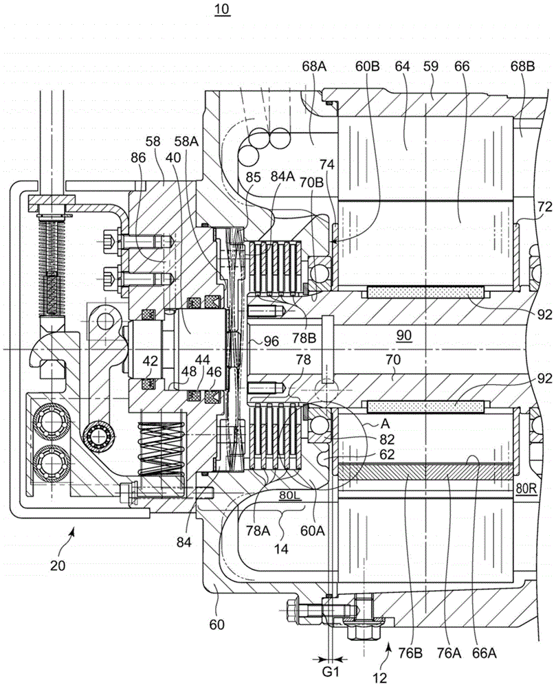
[0017] figure 1 It is a cross-sectional view of a part of the motor 10 according to one embodiment of the present invention taken along a vertical plane including the central axis.

[0018] The motor 10 is a device that integrates an IPM (Interior Permanent Magnet) motor 12 , a wet multi-disc brake mechanism 14 , and a parking brake device 20 .

[0019] The IPM motor 12 includes a stator 64 and a rotor 66 each made of laminated steel plates. The laminated steel plates of the rotor 66 are formed with a plurality of voids 66A extending in the axial direction, and permanent magnets 76A, 76B are embedded in the voids. IPM motors with permanent magnets embedded in the rotor are more efficient than SPM motors with permanent magnets attached to the rotor surface. The laminated steel plates constituting the rotor 66 are integrated with bolts (not shown), and are integrated with the rotor 70 via keys 92 . In addition, it can also be integrated by riveting and bonding without bolts. ...


PUM


Abstract

To provide a motor, a wet type brake, or a wet type clutch in which liquid coolant is sealed and viscous resistance in a gap between a casing and a rotor is reduced. Provided is a motor (10) which includes a casing (60), and a rotor shaft (70) which rotates relative to the casing (60), in which liquid coolant is sealed in the casing (60), and a concave portion (62) is formed on a facing surface (60B) of the casing (60), which faces a rotor (66).

Description

[0001] This application claims priority based on Japanese Patent Application No. 2013-169609 filed on August 19, 2013. The entire contents of this Japanese application are incorporated herein by reference. technical field [0002] The invention relates to a motor, a wet brake and a wet clutch. Background technique [0003] There is known an oil-bath motor in which a motor and a reduction gear are sealed in a space communicating with each other, and lubricating oil is circulated in the space. For example, Patent Document 1 discloses a rotating electric machine in which the rotating shaft of the motor is hollow, and oil-containing refrigerant is sprayed from an external cooling fluid supply unit through a hole in the rotating shaft to a rotor housing space in the housing. [0004] Patent Document 1: Japanese Patent Application Laid-Open No. 11-41861 [0005] If the gap between the housing and the end surface of the rotor is reduced for axial compactness, then the viscous res...

Claims


Application Information

Patent Timeline
Patent Type & Authority Applications(China)
IPC IPC(8): H02K5/04F16D13/58F16D65/00H02K7/102
CPCH02K9/19F16D13/52H02K7/102F16D2121/14B60T13/22F16D2023/123F16D2121/06H02K7/108F16D55/36H02K5/1732
Inventor 石塚正幸恵晶
Owner SUMITOMO HEAVY IND LTD
Why Eureka
Try Eureka