Phase difference hydraulic tightening and loosening type clamp device

A fixture device and phase difference technology, applied in workpiece clamping devices, fluid pressure actuation devices, manufacturing tools, etc., can solve the problems of high pulling frequency, low work efficiency, and tired operation.

Active Publication Date: 2019-09-03
富兰克润滑科技(台州)有限公司
View PDF6 Cites 2 Cited by
  • Summary
  • Abstract
  • Description
  • Claims
  • Application Information

AI Technical Summary

Problems solved by technology

[0002] The existing hydraulic elastic clamp device needs to push the reversing valve by hand, which is very laborious
The existing manual reversing valve is pulled manually, and the frequency of pulling is very high. The manual reversing valve is used for clamping tools. When clamping, it is bent, and when it is released, the valve opens. The operator may need two to three minutes. Pull once, the operation is tiring...

Method used


Image

  • Phase difference hydraulic tightening and loosening type clamp device
  • Phase difference hydraulic tightening and loosening type clamp device
  • Phase difference hydraulic tightening and loosening type clamp device

Examples


Embodiment Construction

[0025] The present invention will be further described below in conjunction with the accompanying drawings of the description.

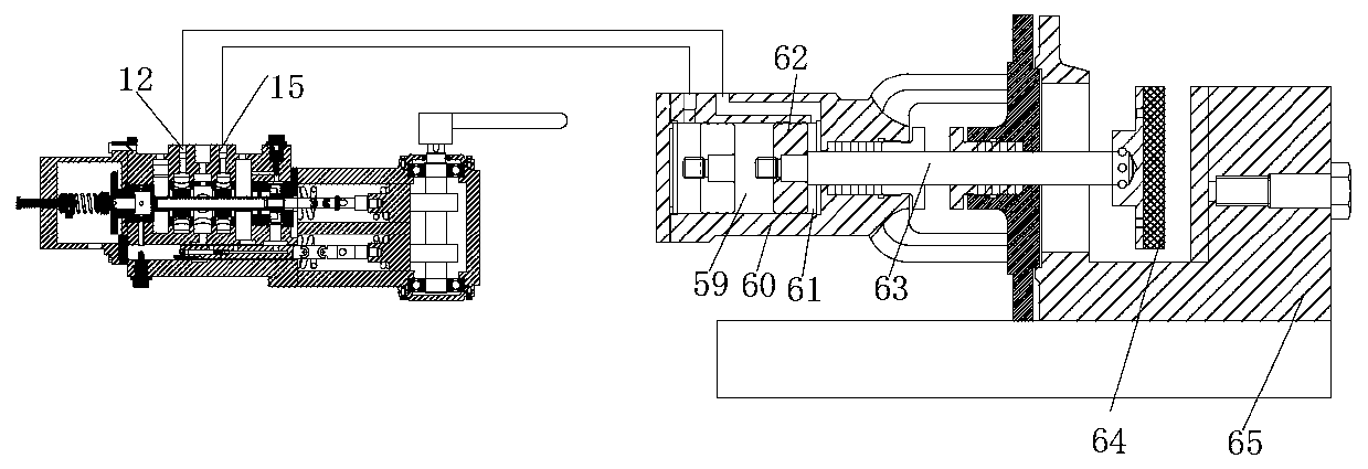
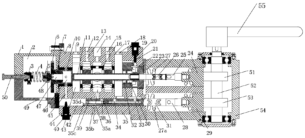
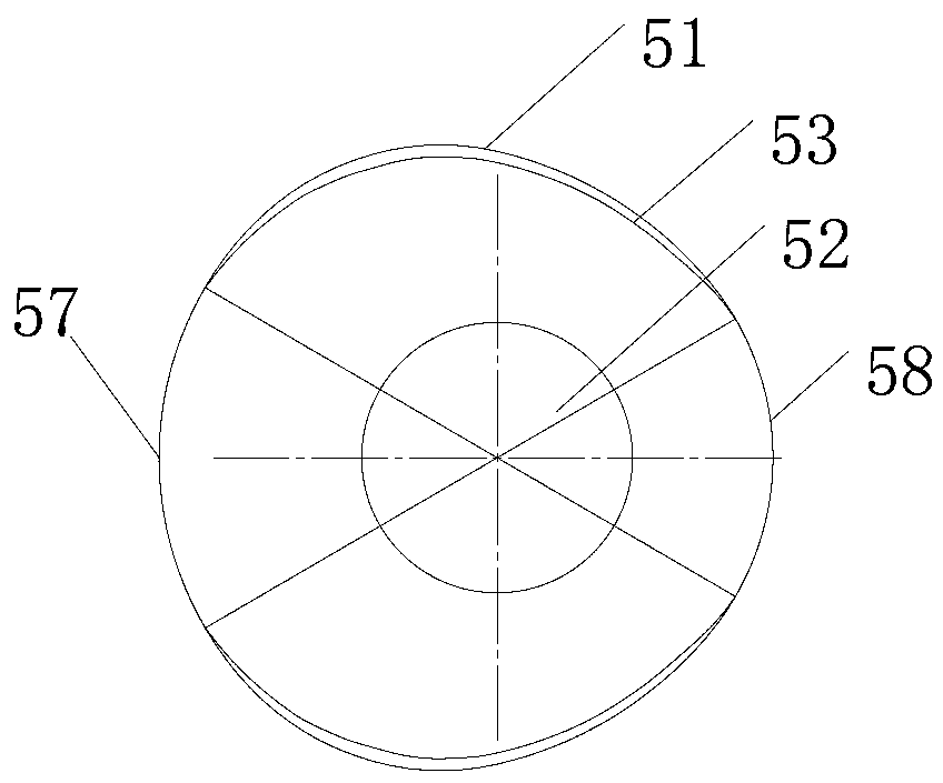
[0026] As shown in the figure, the phase-difference hydraulic elastic clamp device includes a handle 55 and a rotating shaft 52 connected with it. On the rotating shaft 52, a cam 51 and a cam 2 53 are coaxially arranged, and a phase difference is set between the cam 51 and the cam 2 53. , the cam one 51 and the cam two 53 are also simultaneously provided with a stable pressure holding area 57 at the port A and a stable pressure holding area 58 at the port B;

[0027]It also includes a reversing valve. The reversing valve is a valve body composed of housing one 1, housing two 8, and housing three 23. The housing one 1 is provided with an oil return chamber 2 and a return port three 49. The main valve core 11 is arranged in the housing two 8, and the middle part of the main valve core 11 is equipped with a reversing valve sleeve 16. The main valve core...


PUM


Abstract

The invention discloses a phase difference hydraulic tightening and loosening type clamp device, and belongs to the technical field of fatigue testing devices. The phase difference hydraulic tightening variable clamp device comprises a handle and a rotating shaft connected with the handle in a matched mode, wherein the rotating shaft is coaxially provided with a cam I and a cam II, a phase difference is arranged between the cam I and the cam II, and the cam I and the cam II are synchronously provided with an opening A stable pressure maintaining area and an opening B stable pressure maintaining area; and the device further comprises an reversing valve and a clamping tool. According to the technical scheme of the phase difference hydraulic tightening and loosening type clamp device, when the reversing valve is reversed to a reversing opening A, hydraulic oil enters a piston chamber II, a push plate moves leftward, and a clamping plate is loosened; and when the reversing valve is reversed to a reversing opening B, the hydraulic oil enters a piston chamber I, the push plate moves to the right, and the clamping plate clamps. The device has simple and convenient use.

Description

technical field [0001] The invention belongs to the technical field of fatigue testing devices, in particular to a phase difference hydraulic elastic clamp device. Background technique [0002] The existing hydraulic elastic clamp device needs to push the reversing valve by hand, which is very laborious. The existing manual reversing valve is pulled manually, and the frequency of pulling is very high. The manual reversing valve is used for clamping tools. When clamping, it is bent, and when it is released, the valve opens. The operator may need two to three minutes. Pull once, the operation is tiring, and the work efficiency is low. The spool of the existing manual reversing valve reciprocates and cannot rotate. There is a gap between the spool and the valve sleeve. If it is still, the spool will fall off. The spool and hydraulic oil are viscous, and the valve has viscous resistance inside. The oil is dirty, the resistance is greater, and the pulling force needs to be incr...

Claims


Application Information

Patent Timeline
IPC IPC(8): B25B11/00F15B13/02
CPCB25B11/00F15B13/02
Inventor 许静杜加友
Owner 富兰克润滑科技(台州)有限公司
Why Eureka
Try Eureka