
Flow control valve with three-way ball

A technology for flow control valves and through balls, which is applied to valve devices, cocks including cut-off devices, engine components, etc., can solve problems such as troublesome and insufficient precision, and achieve the effect of saving raw materials and better flow limiting effect

Pending Publication Date: 2021-07-27
MILWAUKEE TONGLU VALVE
View PDF0 Cites 2 Cited by
  • Summary
  • Abstract
  • Description
  • Claims
  • Application Information

AI Technical Summary

Problems solved by technology

But for some specific occasions, it is necessary to control the precise flow, and this flow is not the maximum flow of the ball valve, so it is troublesome to adjust to the precise angle, and the accuracy is not enough.

Method used


Image

  • Flow control valve with three-way ball
  • Flow control valve with three-way ball
  • Flow control valve with three-way ball

Examples


Embodiment

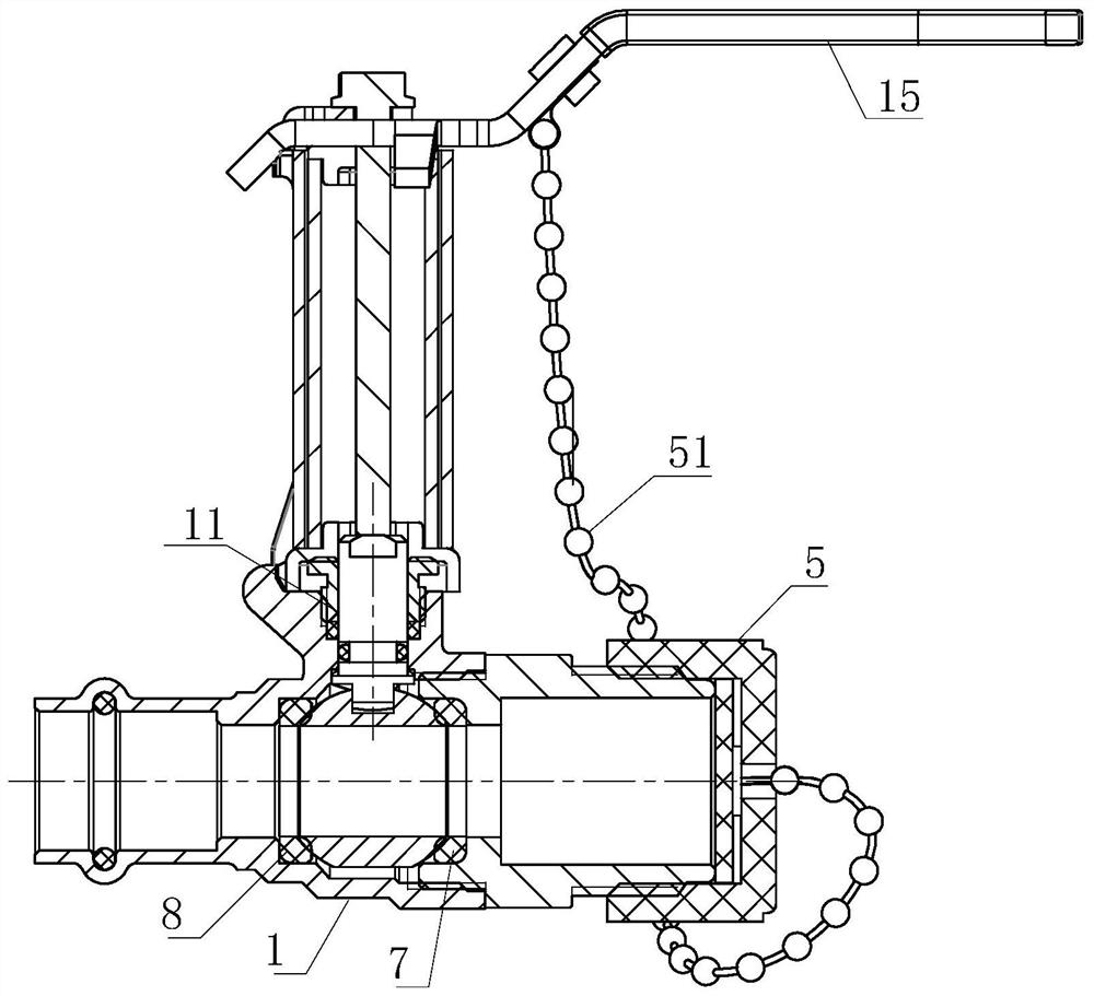
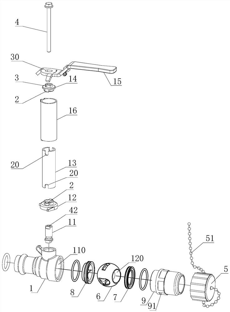
[0035] see Figure 1 to Figure 7 , this embodiment provides a flow control valve with a three-way ball, including a valve body 1, the top of the valve body 1 is rotatably connected to a handle 15 through a valve stem 11, a valve ball 6 is arranged inside the valve body 1, and the The main channel 110 is opened through the valve body 1, the valve ball 6 is rotatably connected in the main channel 110, and the secondary channel 120 is opened through the valve ball 6, when the valve ball 6 is rotated and opened, the main channel 110 and the The secondary channels 120 are connected.

[0036] Both sides of the valve ball 6 are respectively provided with a valve seat 7 and a flow limiting sheet 8, and the valve seat 7 and the flow limiting sheet 8 are located between the outer wall of the valve ball 6 and the inner wall of the main channel 110; the valve seat 7 is Annular, and the area of ​​the annular mouth is larger than the cross-sectional area of ​​the auxiliary flow channel 120...


PUM


Abstract

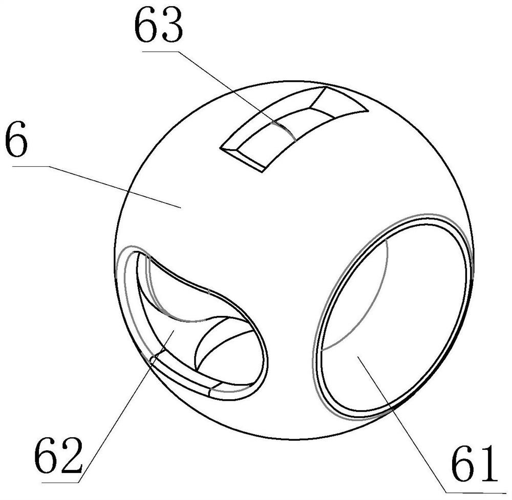
The invention provides a flow control valve with a three-way ball. The flow control valve comprises a valve body, wherein the top of the valve body is rotationally connected with a handle through a valve rod; a valve ball is arranged in the valve body; a valve seat and a flow limiting sheet are arranged on the two sides of the valve ball respectively, and are positioned between the outer wall of the valve ball and the inner wall of a main flow channel; the valve seat is annular; the area of an annular opening is larger than the sectional area of an auxiliary flow channel; a flow limiting opening is formed in the flow limiting sheet; the area of the flow limiting opening is smaller than the sectional area of the auxiliary flow channel; the valve ball is a hollow three-way ball body; three medium through holes are formed in the valve ball; two of the three medium through holes are circular, and the other one is a flow limiting hole; and the area of the flow limiting hole is smaller than that of the circular through hole. The flow control valve is reasonable in design; when the valve is completely opened, the flow of a circulating medium is accurately controlled through the flow limiting sheet and the valve ball; and by the structure, raw materials are saved, and the combination of the flow limiting opening and the flow limiting hole with complex shapes and structures can be realized, so that a better flow limiting effect is achieved.

Description

technical field [0001] The invention relates to the field of ball valves, in particular to a flow control valve with a three-way ball. Background technique [0002] The opening and closing part of the ball valve is a ball with a circular channel, which rotates around the axis perpendicular to the channel, and the ball rotates with the valve stem to achieve the purpose of opening and closing the channel. The ball valve only needs to be operated by rotating 90 degrees and a small rotational torque to close tightly. When the ball valve rotates 90 degrees, the inlet and outlet should all present a spherical surface, so as to close the valve and cut off the flow of the medium; There is no flow resistance. [0003] The flow rate controlled by the ball valve is constant. When it is fully opened, the flux of water is the largest. If you want to adjust the size as follows, you must control the opening angle. But for some specific occasions, it is necessary to control the precise f...

Claims


Application Information

Patent Timeline
Patent Type & Authority Applications(China)
IPC IPC(8): F16K5/06F16K5/08F16K5/12
CPCF16K5/0605F16K5/08F16K5/12
Inventor 王现华姜景田吴燕群齐飞叶娟娟张高良王圣舒
Owner MILWAUKEE TONGLU VALVE
Learn More