
A roll-to-roll laser die-cutting machine

A die-cutting machine, roll-to-roll technology, applied in the direction of laser welding equipment, metal processing equipment, welding equipment, etc., can solve the problems of controlling product quality and cost, raw material damage cost, disadvantages, etc., to reduce adverse effects and improve Product quality, effect of reducing adhesion

Active Publication Date: 2021-12-31
谭清
View PDF10 Cites 0 Cited by
  • Summary
  • Abstract
  • Description
  • Claims
  • Application Information

AI Technical Summary

Problems solved by technology

[0004] The purpose of this invention is to solve the problem that the traditional die-cutting machine needs multiple processing to complete the production of the product, which will bring the possibility of damage to the original material and increase the cost, which is not conducive to the control of the quality and cost of the product

Method used


Image

  • A roll-to-roll laser die-cutting machine
  • A roll-to-roll laser die-cutting machine
  • A roll-to-roll laser die-cutting machine

Examples


Embodiment Construction

[0030] The technical solutions in the embodiments of the present invention will be clearly and completely described below in conjunction with the accompanying drawings in the embodiments of the present invention. Apparently, the described embodiment is only a sub-example of the mechanism of the present invention, rather than the implementation of the whole mechanism example. Based on the embodiments of the present invention, all other embodiments obtained by persons of ordinary skill in the art without making creative efforts belong to the protection scope of the present invention.

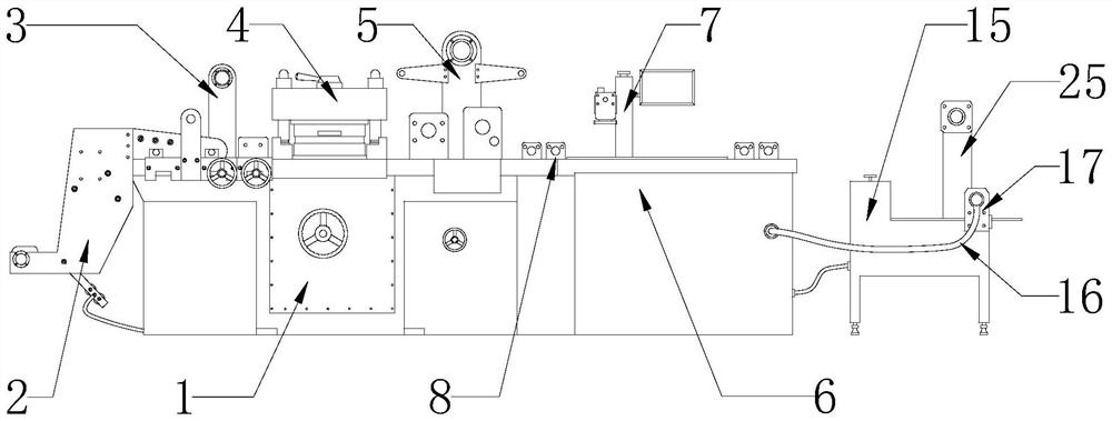
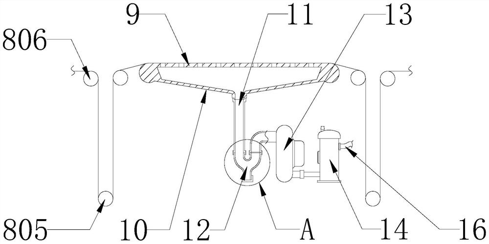
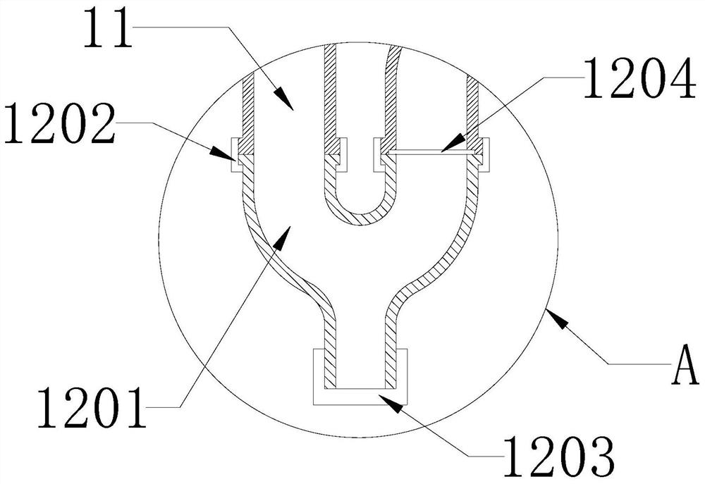
[0031] see Figure 1-9 , in an embodiment of the present invention, a roll-to-roll laser die-cutting machine includes a die-cutting mechanism 1, a first discharge roller 2, a second discharge roller 3, a die-cutting table 4, a first take-up roller 5, a laser Cutting mechanism 6, CCD visual laser machine 7, storage rack 8, slide rail 801, slider 802, guide hole 803, guide rod 804, movable roller 8...


PUM


Abstract

The invention provides a roll-to-roll laser die-cutting machine, which includes a die-cutting mechanism, a first discharge roller and a second discharge roller are arranged at the front end of the die-cutting mechanism, and a die-cutting table is arranged at the middle section of the die-cutting structure. The rear side of the die-cutting table is provided with the first winding roller, and the rear end of the die-cutting mechanism is fixedly connected with a laser cutting mechanism. The front and rear ends of the laser cutting mechanism are equipped with storage racks, and a CCD visual laser machine is installed above it. , the rear end of the laser cutting mechanism is connected with a laser cutting machine, and the laser cutting machine is provided with a material distribution structure and a second receiving roller. The present invention can complete multiple processing of products at one time, reducing the number of processing of products. Reduce the possible adverse effects of the product during transfer and secondary processing, and improve the stability of laser cutting, improve the accuracy of laser marking, and assist the cut product through the setting of the storage rack and the material distribution mechanism The peeling off of waste materials can reduce the occurrence of adhesion between products and waste materials, and has a good development prospect.

Description

technical field [0001] The invention relates to the field of packaging processing, in particular to a laser die cutting machine. Background technique [0002] Die-cutting machine is also called beer machine, laser cutting machine, CNC punching machine, mainly used for die-cutting of some corresponding non-metallic materials, self-adhesive, EVA, double-sided tape, electronics, mobile phone rubber pad, etc. (full cut, half-broken), indentation and hot stamping operations, lamination, automatic waste discharge, die-cutting machine uses steel knife, metal mold, steel wire (or template carved from steel plate), exerts a certain pressure through the embossing plate, and prints Or cardboard rolled and cut into a certain shape. It is an important equipment for post-press packaging processing and molding. [0003] In the existing packaging process, in order to meet the different needs of different customers, it is often necessary to purchase a variety of corresponding equipment to ...

Claims


Application Information

Patent Timeline
Patent Type & Authority Patents(China)
IPC IPC(8): B23K26/38B23K26/362B23K26/70B23K26/14B26F1/38B26D7/27
CPCB23K26/38B23K26/362B23K26/702B23K26/14B26F1/38B26D7/27
Inventor 谭清
Owner 谭清
Learn More