Eureka AIR delivers breakthrough ideas for toughest innovation challenges, trusted by R&D personnel around the world.

Accelerated heat dissipation device for fabricated inner wall heating ventilation air conditioner indoor unit

A technology for HVAC and heat dissipation devices, which is applied in the field of accelerated heat dissipation devices for prefabricated interior wall HVAC internal units, and can solve problems such as poor heat dissipation effect of internal parts, vibration of the air conditioner internal unit, and affecting the heat dissipation effect and life of the heat dissipation device. , to achieve the effect of good heat dissipation and fast heat dissipation

Inactive Publication Date: 2021-07-27
江顺琴
View PDF1 Cites 0 Cited by
  • Summary
  • Abstract
  • Description
  • Claims
  • Application Information

AI Technical Summary

Problems solved by technology

[0007] In order to solve the above-mentioned technical problems, the present invention provides an accelerated heat dissipation device for an assembled interior wall HVAC internal unit to solve the problem of only dissipating the heat generated on the surface of the shell during heat dissipation. Since the internal unit of the air conditioner is a sealed structure, the The heat dissipation effect of the internal parts of the air conditioner is poor. During the heat dissipation process of the heat dissipation device, the dust in the air will be brought into the interior of the heat dissipation device, which will affect the heat dissipation effect and life of the heat dissipation device. The air conditioner internal unit will vibrate when it is working. After the cooling device is installed, the bolts will loosen, which will cause the problem that the cooling device is not installed firmly.

Method used


Image

  • Accelerated heat dissipation device for fabricated inner wall heating ventilation air conditioner indoor unit
  • Accelerated heat dissipation device for fabricated inner wall heating ventilation air conditioner indoor unit
  • Accelerated heat dissipation device for fabricated inner wall heating ventilation air conditioner indoor unit

Examples


Embodiment

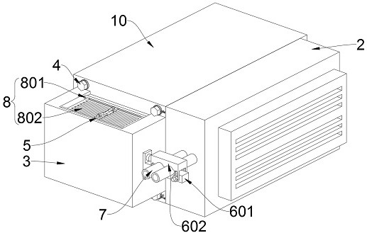
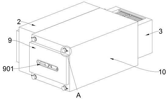
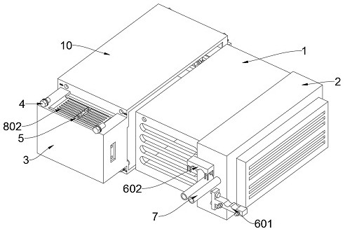
[0065] as attached figure 1 To attach Figure 11 Shown:

[0066] The present invention provides a prefabricated inner-wall heating, ventilation and air-conditioning internal unit accelerated heat dissipation device, including an air-conditioning internal unit 1;

[0067] One side of the air conditioner inner unit 1 is provided with an exhaust seat 2;

[0068] Protective shell A3, the protective shell A3 is located on the right side of the air conditioner inner unit 1;

[0069] Cleaning mechanism, above which there is a connecting bar with a rectangular structure;

[0070] A pipeline support mechanism 6, the pipeline support mechanism 6 is installed on one side of the protective shell A3;

[0071] The air-conditioning duct 7 is arranged on one side of the air-conditioning inner unit 1, and the air-conditioning duct 7 has two components;

[0072] The heat dissipation mechanism 8 is fixed on the inner side of the protective shell A3 by bolts;

[0073] Protective shell B9, t...


PUM


Abstract

The invention provides an accelerated heat dissipation device for a fabricated inner wall heating ventilation air conditioner indoor unit, and belongs to the technical field of heat dissipation of air conditioner indoor units. The problems of heat dissipation of air conditioner indoor units and looseness prevention of bolts are solved. The accelerated heat dissipation device comprises the air conditioner indoor unit. An exhaust seat is arranged on one side of the air conditioner indoor unit. A protective shell A is arranged on the right side of the air conditioner indoor unit. A connecting cross rod of a rectangular structure is arranged above a cleaning mechanism. A pipeline supporting mechanism is mounted on one side of the protective shell A. A heat dissipation mechanism is arranged on the protective shell A, the effect of conveying air to the inner side is achieved through the arrangement of an air inlet fan, a filtering water tank is arranged at the bottom of the air inlet fan, the air inlet fan conveys the air to the filtering water tank for impurity filtering, and the filtered air can flow outwards to pass through the inner side of a heat dissipation shell; and the filtered air can be used for filtering the heat dissipation shell and keeping the interior of the heat dissipation shell clean and tidy, so that the heat dissipation effect of heat dissipation fins of the heat dissipation shell is better.

Description

technical field [0001] The invention belongs to the technical field of heat dissipation of an air conditioner inner unit, and more specifically relates to an accelerated heat dissipation device for an assembled inner wall HVAC inner unit. Background technique [0002] The indoor unit is an air outlet for sending cold air, which is actually the same as the conventional household air conditioner. The conventional household air conditioner generally has one outdoor unit and one indoor unit, while the central air conditioner generally has one outdoor unit and multiple indoor units. The internal unit of the air conditioner is generally called terminal equipment, and there are many types. The internal unit of the central air conditioner is composed of two parts: the internal unit control mechanism and the air outlet mechanism, and the two parts are separated by a partition. In HVAC, a central air conditioner will be installed for cooling and heating. [0003] For example, the pat...

Claims


Application Information

Patent Timeline
Patent Type & Authority Applications(China)
IPC IPC(8): F24F1/0007F24F13/00F24F13/28F24F11/39F24F11/52B01D46/00B01D46/10B01D47/02
CPCF24F1/0007F24F13/00F24F13/28F24F11/39F24F11/52B01D46/10B01D47/02B01D47/021B01D46/681
Inventor 江顺琴
Owner 江顺琴
Why Eureka
Eureka Blog
Learn More