Flowmeter pipe section anti-freezing structure and method

A technology of flowmeter and pipe section, which is applied in the field of antifreeze structure of flowmeter pipe section, which can solve the problems of pipe freezing, inability to realize circulation, and pipe leakage, etc., and achieve the effect of preventing freezing

Pending Publication Date: 2021-07-27
MAXTOR INSTR CO LTD
View PDF1 Cites 0 Cited by
  • Summary
  • Abstract
  • Description
  • Claims
  • Application Information

AI Technical Summary

Problems solved by technology

The commonly used unit in engineering is m3 / h, which can be divided into instantaneous flow rate (Flow Rate) and cumulative flow rate. The instantaneous flow rate is the amount that passes through the effective cross-section of a closed pipe or open channel per unit time. The flowing material can be gas, liquid, or solid; When the flowmeter is used, the pipeline is prone to freezing and leakage. However, various flowmeter pipelines on the market still have various problems.
[0003] For example, the authorized announcement number is CN110243426A, which discloses an antifreeze structure and method for a flowmeter pipe section. Although it has the characteristics of simple and reasonable structure, strong pressure resistance and antifreeze ability, and convenient maintenance, it is especially suitable for high-pressure media in pipelines or pipelines. On-site working conditions where the internal medium is easy to freeze and damage the flow meter, it can be widely used in pipe-type flowmeter instruments, especially suitable for the anti-freeze structure of small-diameter anti-freeze water meters, but it does not solve the problem that the existing pipes are prone to freezing and cannot be realized Circulation, as well as the inability to achieve thawing and pressure relief, and the pipeline is prone to leakage, resulting in the problem of freezing the pipeline. For this reason, we propose an antifreeze structure and method for the flowmeter pipe section

Method used


Image

  • Flowmeter pipe section anti-freezing structure and method
  • Flowmeter pipe section anti-freezing structure and method
  • Flowmeter pipe section anti-freezing structure and method

Examples


Embodiment Construction

[0032] The following will clearly and completely describe the technical solutions in the embodiments of the present invention with reference to the accompanying drawings in the embodiments of the present invention. Obviously, the described embodiments are only some, not all, embodiments of the present invention. Based on the embodiments of the present invention, all other embodiments obtained by persons of ordinary skill in the art without making creative efforts belong to the protection scope of the present invention.

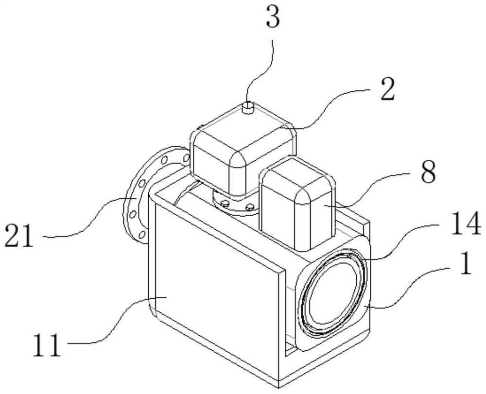
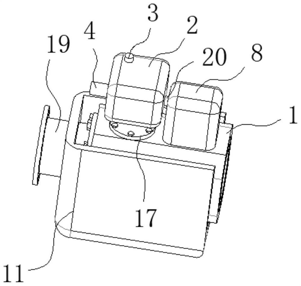
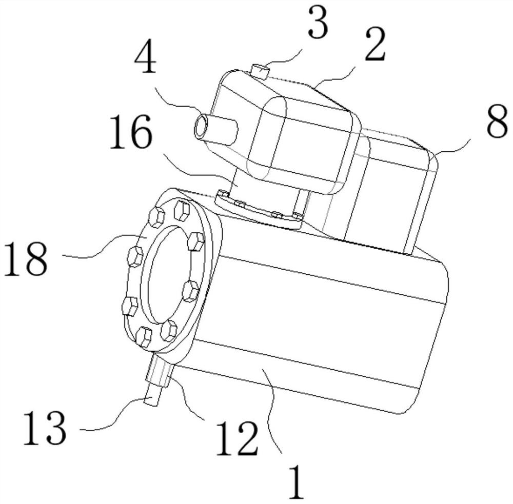
[0033] see Figure 1-Figure 6 , the present invention provides a technical solution: an antifreeze structure for a flowmeter pipe section, including a flowmeter pipe 1, a control box 2 is fixedly installed on the flowmeter pipe 1, and an external Ambient temperature detection head 3, one side of the control box 2 is fixedly provided with a pressure relief port 4, the bottom of the control box 2 is fixedly installed with a detection head connection column 5, an...


PUM


Abstract

The invention discloses a flowmeter pipe section anti-freezing structure which comprises a flowmeter pipeline. A control box is installed on the flowmeter pipeline, an electromagnetic valve controller is installed on one side of the flowmeter pipeline, a liquid carrying box is arranged at the bottom of the flowmeter pipeline, a heating cavity is formed in the outer wall of the flowmeter pipeline, and a plurality of groups of heating rings are mounted in the heating cavity. The using method of the anti-freezing structure of the flowmeter pipe section comprises the following steps of S1, controlling a detection flow and an environment condition in a pipeline; S2, detecting the environment temperature through an external environment temperature detection head at the upper part of the control box; S3, enabling the control box to control the heating ring to heat the flowmeter pipeline; and S4, judging whether leakage occurs or not through the liquid carrying box. According to the invention, icing detection and heating unfreezing can be realized, and leakage detection can also be realized too.

Description

technical field [0001] The invention belongs to the technical field of flowmeter pipes, and in particular relates to an antifreeze structure of a flowmeter pipe section, and also relates to a method for using the antifreeze structure of a flowmeter pipe section. Background technique [0002] Flow Meter: An instrument that indicates the measured flow rate and / or the total amount of fluid over a selected time interval. Simply put, it is an instrument used to measure the flow of fluid in pipelines or open channels. Flowmeters are further divided into differential pressure flowmeters, rotameters, throttling flowmeters, slit flowmeters, volumetric flowmeters, electromagnetic flowmeters, ultrasonic flowmeters, etc. Classified by medium: liquid flowmeter and gas flowmeter, measurement is the eye of industrial production. Flow measurement is one of the components of measurement science and technology, and it is closely related to national economy, national defense construction and...

Claims


Application Information

Patent Timeline
Patent Type & Authority Applications(China)
IPC IPC(8): G01F15/00G01F15/10F17D5/02
CPCF17D5/02G01F15/00G01F15/10
Inventor 孙卫国邹孝旺
Owner MAXTOR INSTR CO LTD
Why Eureka
Try Eureka