

A phase-controlled reactor type dynamic reactive power compensation device
A compensating device and reactor technology, applied in substation/distribution device housing, substation/switchgear cooling/ventilation, substation/switch layout details, etc., can solve the problem of increased power loss, insulation damage, constant shaking, etc. Problems, to avoid heat dissipation speed, speed up the effect of heat dissipation
- Summary
- Abstract
- Description
- Claims
- Application Information
AI Technical Summary
Problems solved by technology
Method used
Image

Examples
Embodiment 1
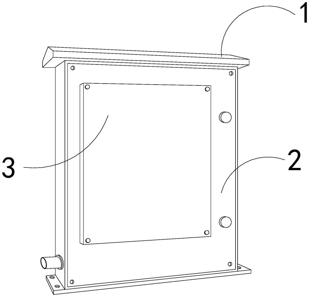
[0028] For example figure 1 -example Figure 5 Shown:
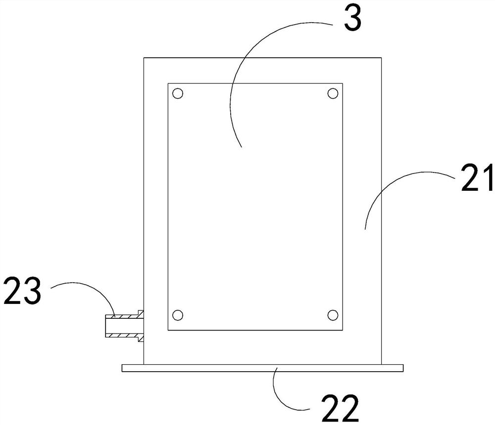
[0029] The invention provides a phase-controlled reactor type dynamic reactive power compensation device, the structure of which includes a top cover 1, a compensation cabinet 2, and a sealing plate 3, the sealing plate 3 is riveted to the front end of the compensation cabinet 2, and the compensation cabinet 2 is connected to the bottom of the top cover 1; the compensation cabinet 2 includes a cabinet body 21, a base 22, and an adapter 23, the bottom of the cabinet body 21 is attached to the upper surface of the base 22, and the adapter 23 is welded on the left side of the base 22.
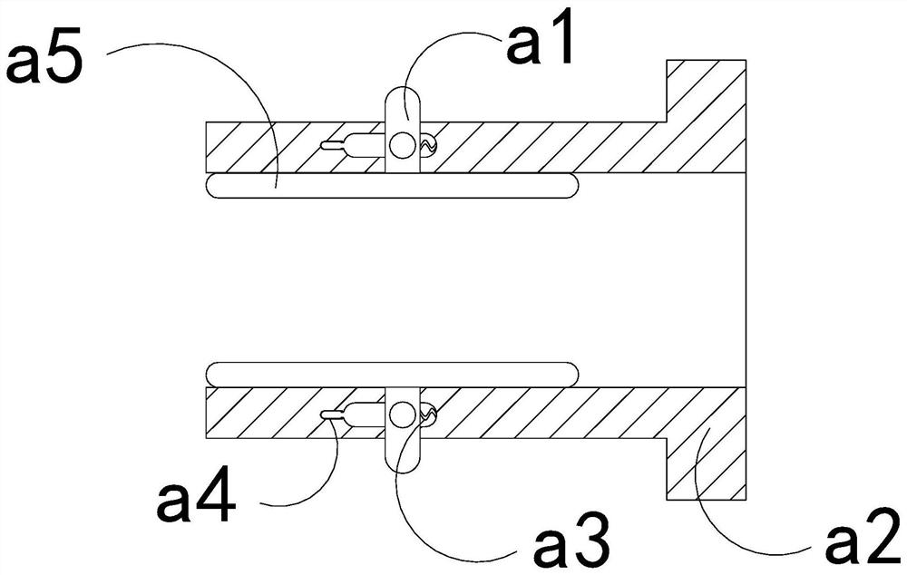
[0030] Wherein, the adapter 23 includes a booster block a1, an outer tube a2, a pull-back bar a3, a slot a4, and a clamping plate a5, the booster block a1 is engaged with the inner part of the outer tube a2, The pull bar a3 is installed between the right side of the inner wall of the outer tube a2 and the right side of the booster block a1...
Embodiment 2
[0036] For example Figure 6 -example Figure 9 Shown:
[0037] Wherein, the clamping plate a5 includes an inscribed cavity c1, a plate body c2, and a vent c3, the inscribed cavity c1 is embedded in the inner position of the plate c2, the vent c3 communicates with the plate c2, the vent There are two openings c3, which are evenly distributed in parallel on the left end of the plate body c2, and can communicate with the outside world through the ventilation opening c3, so that the air flow from the outside can enter the interior of the internal connection cavity c1 through the ventilation opening c3.
[0038]Wherein, the internal connection cavity c1 includes a heat dissipation strip c11, a connection port c12, and a heat inlet c13. The heat dissipation strip c11 runs through the inner position of the heat inlet c13. At the bottom position, the heat dissipation bar c11 adopts a strip structure made of aluminum metal with strong heat dissipation. Through the heat dissipation...
PUM
 Abstract
Description
Claims
Application Information