Clamping device facilitating automatic welding of round pipe

A clamping device and automatic welding technology, applied in welding equipment, auxiliary devices, auxiliary welding equipment, etc., can solve problems such as low efficiency, and achieve the effect of convenient welding and high welding efficiency

Pending Publication Date: 2021-07-30
上海坦岩自动化工程有限公司
View PDF9 Cites 0 Cited by
  • Summary
  • Abstract
  • Description
  • Claims
  • Application Information

AI Technical Summary

Problems solved by technology

[0004] In view of the above-mentioned related technologies, the inventor believes that this method of welding round pipes requires welders to weld a part of the arc edge during

Method used


Image

  • Clamping device facilitating automatic welding of round pipe
  • Clamping device facilitating automatic welding of round pipe
  • Clamping device facilitating automatic welding of round pipe

Examples


Example Embodiment

[0031] Contraction below Figure 1-4 Further detailed description of the present application.

[0032] In this application example, it is disclosed a clamping device 3 that facilitates the automatic welding of the circular tube.

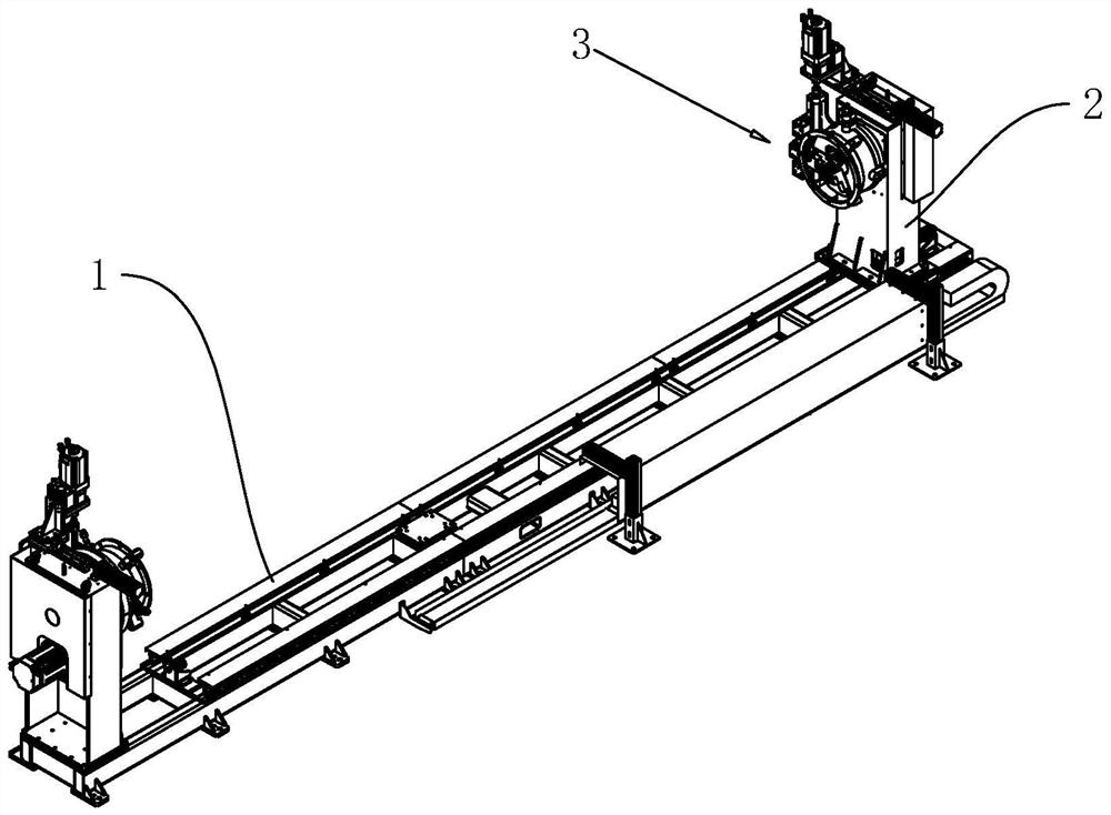
[0033] Refer figure 1 A clamping device 3 that facilitates the automatic welding of the round tube, including the base 1, both ends of the base 1, and the mounting seat 2 is provided, and the mounting seat 2 is provided with a clamping device 3 for clamping a circular tube, welding round tube. In the process, the round tube is held on one of the clamping device 3 at one end, and the other end is sandwiched on another clamping device 3.

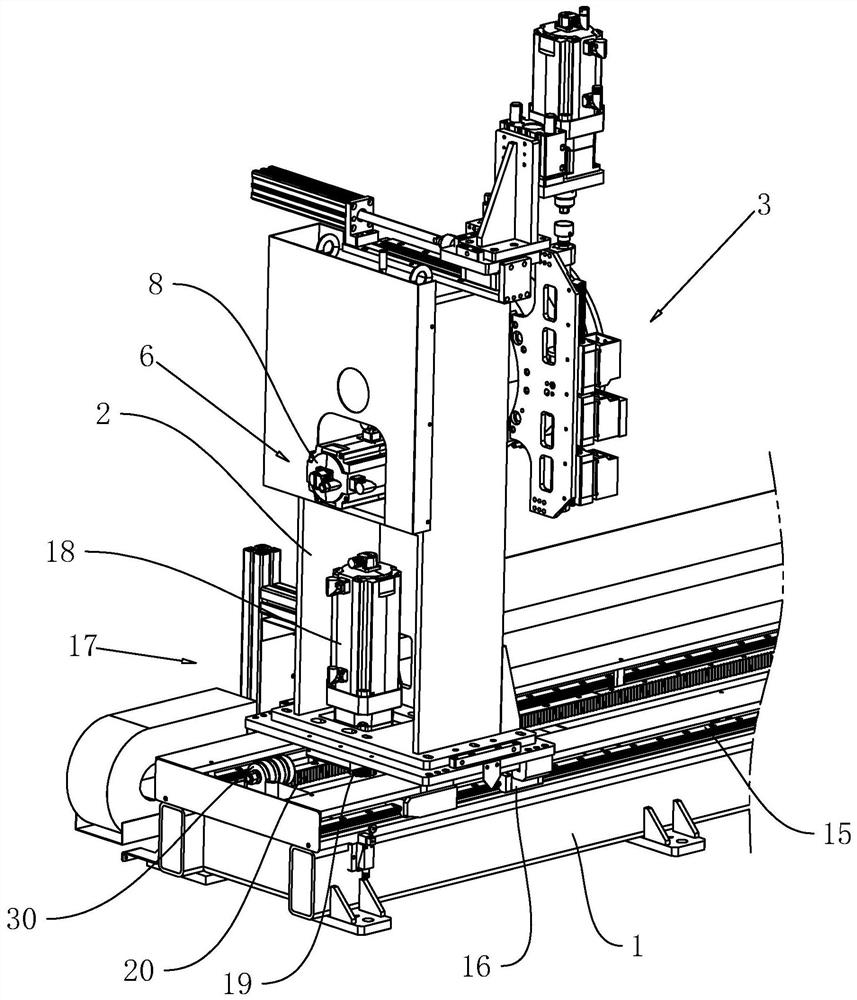
[0034] Refer figure 2 One of the mounting seats 2 slides on the base 1, so that the round tube of different lengths between the two holding means 3 can be mounted, and both sides of the base 1 are provided with a first rail 15, the first guide rail 15. For the straight rail, two first slider 16 is fixed to the bottom of t...


PUM


Abstract

The invention relates to the field of welding tools, in particular to a clamping device facilitating automatic welding of a round pipe. The clamping device comprises a base, mounting seats are arranged at the two ends of the base, and clamping device bodies for clamping the end part of the round pipe are arranged on the opposite surfaces of the two mounting seats; and each clamping device body comprises a mounting disc which rotates above the base, a three-jaw chuck which is coaxially fixed on the mounting disc and is used for clamping the round pipe, and a first driving mechanism which is arranged on the mounting disc and is used for driving the mounting disc to rotate. The clamping device has the effects of facilitating welding and being high in welding efficiency.

Description

technical field [0001] The present application relates to the field of welding equipment, in particular to a clamping device for automatic welding of round pipes. Background technique [0002] In the process of producing round pipes, the existing pipe fittings manufacturers need to weld the ends of the round pipes. Some pipe fittings need full welding, such as welding flanges on the outer wall of the end of the round pipes. Some pipe fittings need to be welded. Assembly welding. [0003] Usually, existing manufacturers directly place the round tube on the welding table, weld a part of the arc, and then continue to rotate and continue welding during the welding process, so that the edge of the whole round tube is welded bit by bit. [0004] In view of the above-mentioned related technologies, the inventor believes that this method of welding round pipes requires welders to weld a part of the arc edge during the welding process, then rotate the round pipe, and repeat the abov...

Claims


Application Information

Patent Timeline
IPC IPC(8): B23K37/053B23K37/047B23K37/02
CPCB23K37/053B23K37/0533B23K37/047B23K37/02Y02P70/10
Inventor 程汪敏余世春温秋阳程文兵李舜程文鹏
Owner 上海坦岩自动化工程有限公司
Why Eureka
Try Eureka