
Steel wire rope reduction gearbox

A technology of steel wire rope and reduction box is applied in the field of steel wire rope synthesizer, which can solve the problems that the quality of the steel wire rope does not meet the standard, and the 100%±30% back-twisting of the cable cannot be realized.

Inactive Publication Date: 2021-07-30
HEFEI SMARTER TECH GROUP CORP
View PDF5 Cites 0 Cited by
  • Summary
  • Abstract
  • Description
  • Claims
  • Application Information

AI Technical Summary

Problems solved by technology

[0003] The main reduction box of the cage-type twisting machine in the prior art can realize the untwisted state of the cable is basically a 100% untwisted mode, but cannot realize the untwisted mode of 100% ± 30% of the cable, or other percentage untwisted modes. Leading to the substandard quality of steel wire rope synthesis

Method used


Image

  • Steel wire rope reduction gearbox
  • Steel wire rope reduction gearbox
  • Steel wire rope reduction gearbox

Examples


Embodiment Construction

[0031] The following will clearly and completely describe the technical solutions in the embodiments of the present invention with reference to the accompanying drawings in the embodiments of the present invention. Obviously, the described embodiments are only some, not all, embodiments of the present invention. Based on the embodiments of the present invention, all other embodiments obtained by persons of ordinary skill in the art without making creative efforts belong to the protection scope of the present invention.

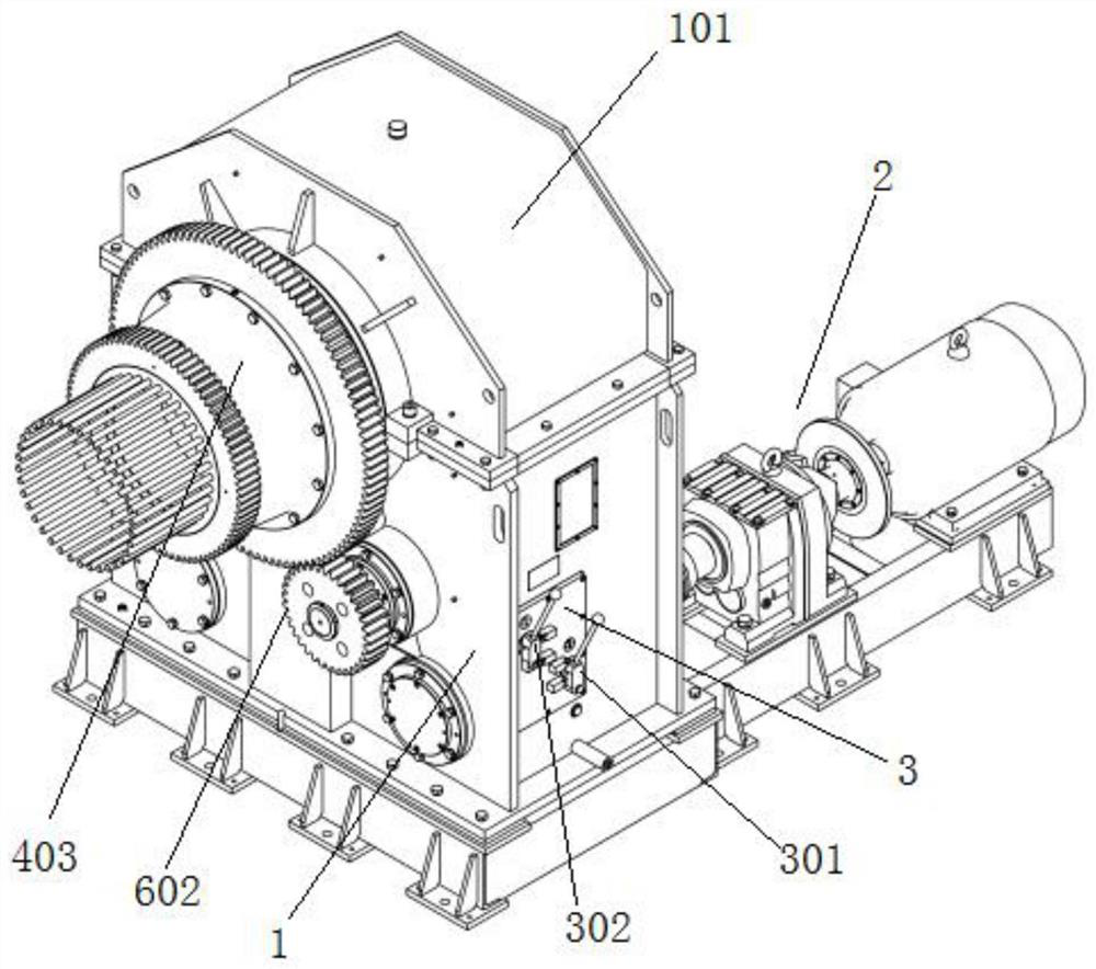
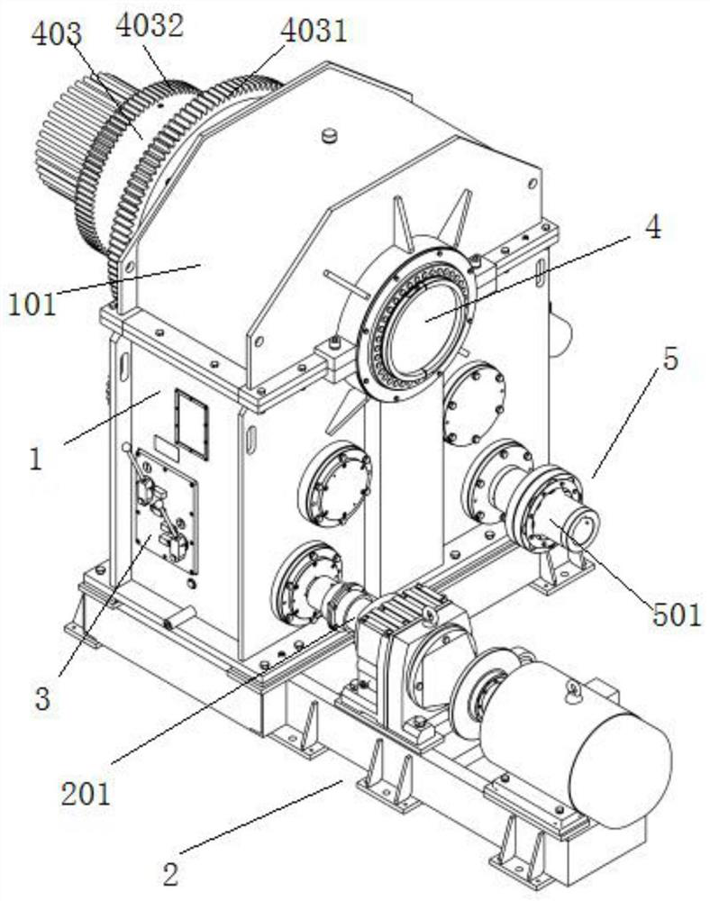
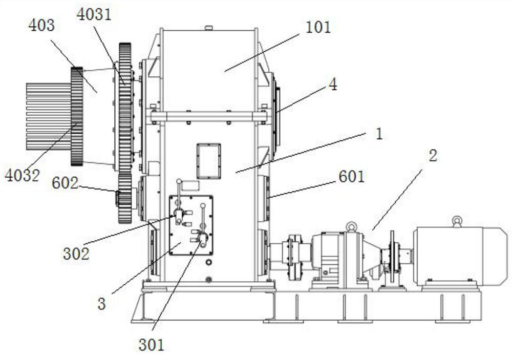
[0032] see Figure 1-9 , in an embodiment of the present invention, a steel wire rope reduction box includes a reduction box body 1, a first main shaft 4 is arranged on the first main shaft 4, and a winch for stranding the steel wire rope is provided at the output end of the first main shaft 4 Mechanism, the two sides of the bottom of the reduction box body 1 are respectively provided with a back-twist driving device 2 and a main input load 5, and a transmissi...


PUM


Abstract

The invention discloses a steel wire rope reduction gearbox. The reduction gearbox comprises a reduction gearbox body, a first main shaft is arranged on the reduction gearbox body, a winch mechanism for stranding steel wire ropes is arranged at the output end of the first main shaft, a back-twist driving device and a main input load are arranged on the two sides of the bottom of the reduction gearbox body respectively, a transmission mechanism II is arranged between the main input load and the first main shaft and is in transmission connection with the main input load and the first main shaft, and a transmission mechanism I is arranged between the back-twist driving device and the reduction gearbox body and is in transmission connection with the back-twist driving device and the reduction gearbox body. According to the reduction gearbox, during use, when 100% non-back-twist in the steel wire rope synthesis process or 100% back-twist in the steel wire rope synthesis process is realized, the main input load serves as a power source, rotation of a winch in the winch mechanism is realized, and meanwhile, back-twist of different percentages in the steel wire rope reduction gearbox synthesis process can be realized through the back-twist driving device.

Description

technical field [0001] The invention belongs to the technical field of steel wire rope synthesis machines, in particular to a steel wire rope speed reducer. Background technique [0002] In the process of producing cables or steel wire ropes, one of the processes is to wind multiple copper wires or steel wires together. This process is called stranding. The operating equipment for this process is a cage stranding machine, and the driving equipment for the cage stranding machine is Gearbox. At present, in the cable manufacturing and steel wire rope manufacturing industries, 100% untwisting of the cable is required when twisting steel wires, strands and other cables; 100% of the cable is required when twisting cables such as flat wires, fan-shaped wires, and special-shaped wires. % No back twisting; 100% ± 30% back twisting is required when twisting some special strands, special-shaped wires and other cables. [0003] The main reduction box of the cage-type twisting machine ...

Claims


Application Information

Patent Timeline
IPC IPC(8): F16H3/20F16H57/023F16H57/02F16H63/30
CPCF16H3/20F16H57/023F16H57/02F16H63/30
Inventor 汪红军林帅熊李磊
Owner HEFEI SMARTER TECH GROUP CORP
Learn More