Photography lamp soft light box with adjustable size
A photographic light and adjustable technology, applied in the field of soft boxes, can solve the problems of dim light, inconvenient adjustment of the size of the soft box, uneven illumination, etc., and achieve the effect of light overall structure
- Summary
- Abstract
- Description
- Claims
- Application Information
AI Technical Summary
Problems solved by technology
Method used
Image
Examples
Embodiment 1
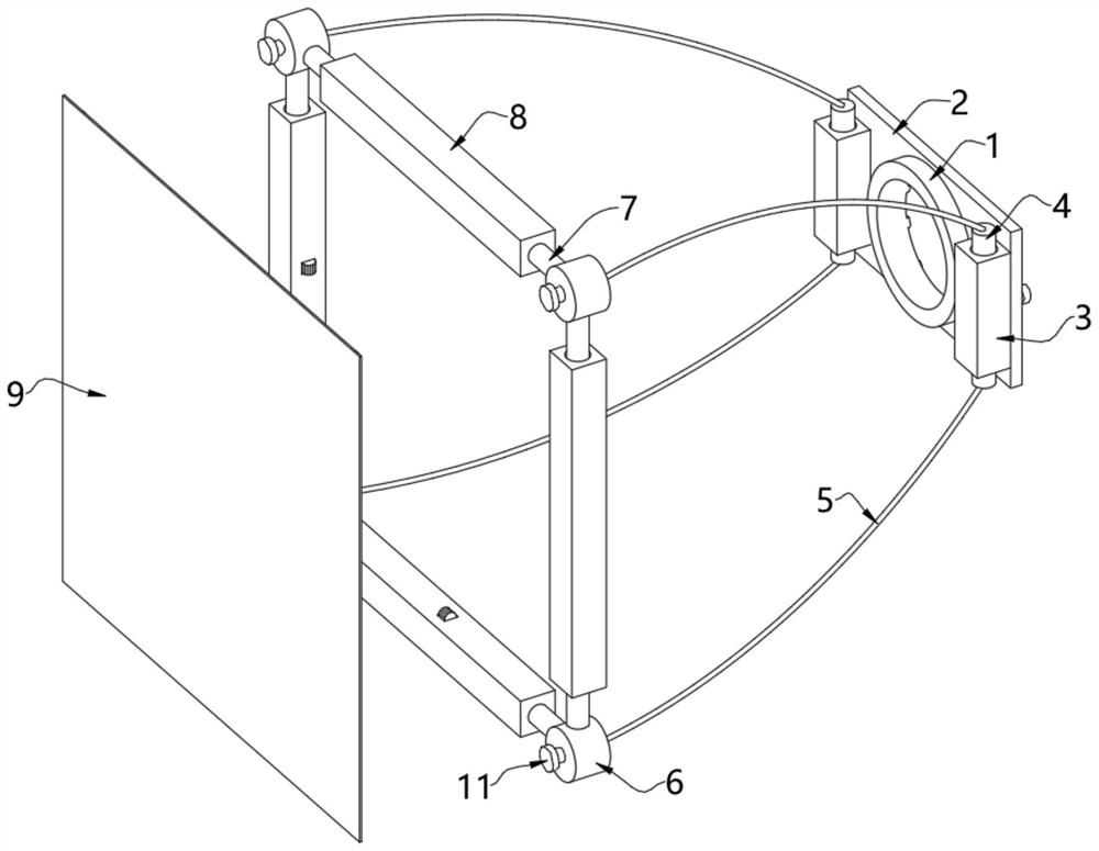
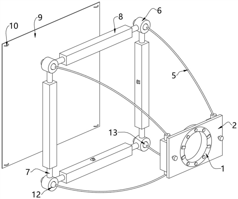
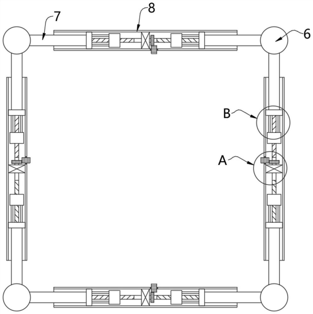
[0056] see Figure 1-Figure 6 , a photographic light softbox with adjustable size, comprising a snap ring 1, a mounting plate 2 is fixedly installed on the outer wall of the snap ring 1, and a fixing tube 3 is fixedly installed on the left and right sides of the outer wall of the mounting plate 2, and the two fixing tubes The interior of 3 is provided with a rotating column 4 for rotation, and the locking device arranged inside the fixed cylinder 3 is used to lock the position of the rotating column 4. The locking device includes a limit plate 26, a card slot 28, a screw nut 29, a bolt 30 and a locking device. Block 31, the inside of the fixed cylinder 3 is provided with a rotating groove, the rotating column 4 is rotated and arranged in the inside of the rotating groove, the upper and lower sides of the outer wall of the rotating column 4 are fixedly equipped with a limit plate 26, and the limit plate 26 is movably arranged in the limit groove On the inwall of 27, limit groov...
Embodiment 2
[0068] see Figure 7-Figure 10 , on the basis of Embodiment 1, the side of the snap ring 1 facing the elastic support frame 5 is also fixedly installed with a soft light tube 32, and the inner wall of the soft light tube 32 is evenly fixed with a number of light equalizing members 34, and several light equalizing members 34 are fixedly installed on the inner wall of the soft light tube 32. A light-blocking piece 33 is fixedly installed between the light pieces 34, and the light-blocking piece 33 is used to block direct light. In between, the end of the positioning column 35 facing away from the elastic support frame 5 is formed with a light blocking groove 36, the inner wall of the snap ring 1 is clamped with a light source, and the side of the light source facing the elastic support frame 5 is provided with a lamp cap, and the position of the lamp cap is in line with the barrier. The position of the light slot 36 is corresponding, and the shape of the outer wall of the lamp c...
PUM
 Abstract
Description
Claims
Application Information
 - R&D
- Intellectual Property
- Life Sciences
- Materials
- Tech Scout
- Unparalleled Data Quality
- Higher Quality Content
- 60% Fewer Hallucinations
Browse by: Latest US Patents, China's latest patents, Technical Efficacy Thesaurus, Application Domain, Technology Topic, Popular Technical Reports.
© 2025 PatSnap. All rights reserved.Legal|Privacy policy|Modern Slavery Act Transparency Statement|Sitemap|About US| Contact US: help@patsnap.com


