CTP liquid cooling plate and battery system

A liquid cold plate and battery module technology, applied in the direction of secondary batteries, circuits, electrical components, etc., can solve the problems of large temperature difference of liquid cold plate, thick liquid cold plate, etc., to improve energy density, reduce thickness and effect of weight

Pending Publication Date: 2021-07-30
HUBEI JINQUAN NEW MATERIALS CO LTD
View PDF0 Cites 0 Cited by
  • Summary
  • Abstract
  • Description
  • Claims
  • Application Information

AI Technical Summary

Problems solved by technology

[0004] The first object of the present invention is to provide a CTP liquid cold plate, which can solve the problem of large temperature difference between different parts of the liquid cold plate in the prior art
The second purpose of the present inven

Method used


Image

  • CTP liquid cooling plate and battery system
  • CTP liquid cooling plate and battery system
  • CTP liquid cooling plate and battery system

Examples


Example Embodiment

[0023] The present disclosure embodiment will be described in detail below with reference to the accompanying drawings.

[0024] The embodiments of the present disclosure can be easily understood by those skilled in the

[0025] CTP liqui...


PUM

PropertyMeasurementUnit
Heightaaaaaaaaaa
Thicknessaaaaaaaaaa

Abstract

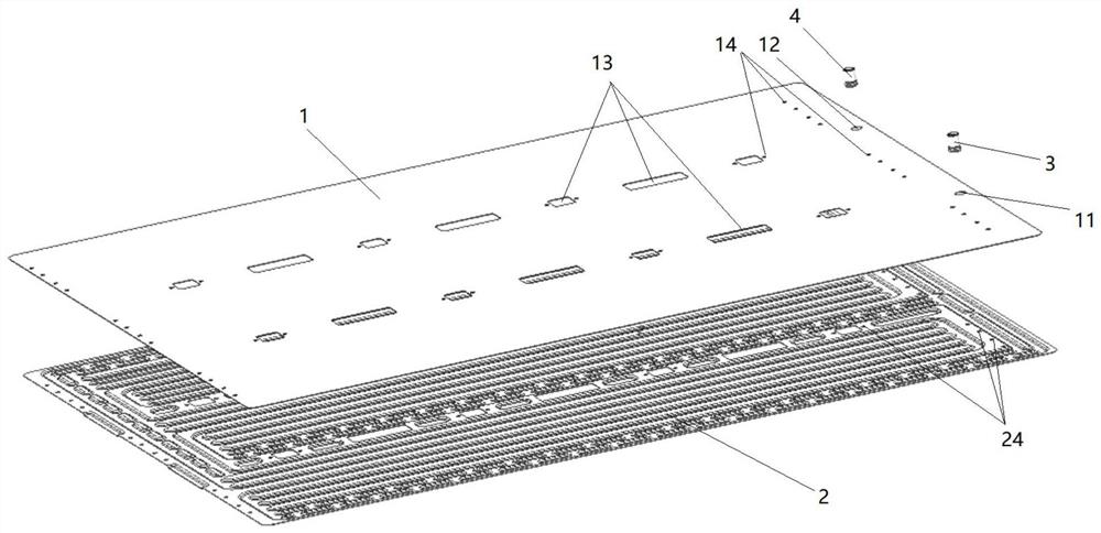
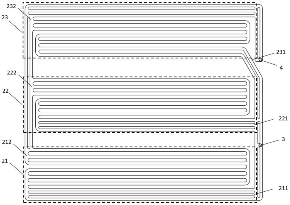
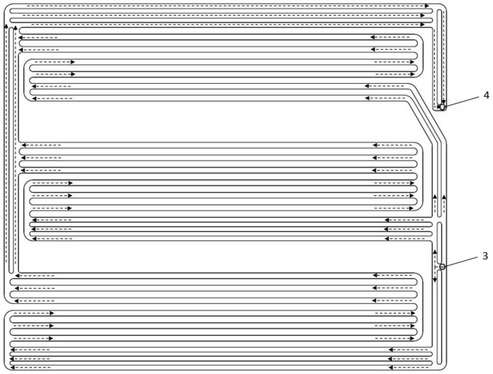
The invention discloses a CTP liquid cooling plate and a battery system. The CTP liquid cooling plate comprises an upper plate, a lower plate, a water inlet pipe and a water outlet pipe, wherein the upper plate is connected with the lower plate; the water inlet pipe and the water outlet pipe are mounted on the upper plate; at least two groups of runners are arranged between the upper plate and the lower plate, each group of runner comprises an inlet and an outlet, each inlet is communicated with the water inlet pipe, and each outlet is communicated with the water outlet pipe. According to the CTP liquid cooling plate, the total thickness is only 5 mm, and compared with 9-10 mm in the prior art, the thickness and the weight of the liquid cooling plate are reduced to a great extent, and the energy density is improved. In addition, according to the CTP liquid cooling plate, the flow channels are divided into at least two groups, and the flow channels in each group are connected in parallel. Each group of runners cools one battery module, and the series-parallel combined runner design under each battery module is beneficial to the realization of balanced cooling of the battery modules.

Description

technical field [0001] The invention relates to the technical field of liquid cold plate structure design, in particular to a CTP liquid cold plate applied to the top of a battery module and a battery system. Background technique [0002] The liquid cold plate is a key component in the battery system, and its function is to reduce the working temperature of the power battery pack in the power battery system. An effective battery thermal management system is the basis for ensuring its good performance. Studies have shown that the performance of power batteries is mainly restricted by the battery temperature, and the temperature of the battery has a key impact on the service life and performance of the battery. Therefore, the structural design of the liquid cooling device of the battery module is very important. [0003] At present, the liquid cooling plate of the CTP (Cell to PACK) method is mostly placed at the bottom of the battery module. It is also because the cold pla...

Claims


Application Information

Patent Timeline
IPC IPC(8): H01M10/613H01M10/617H01M10/6554H01M10/6556H01M10/6568
CPCH01M10/613H01M10/617H01M10/6554H01M10/6556H01M10/6568Y02E60/10
Inventor 闫仕伟刘华俊阎明瀚徐宇虹江吉兵
Owner HUBEI JINQUAN NEW MATERIALS CO LTD
Why Eureka
Try Eureka