Eureka AIR delivers breakthrough ideas for toughest innovation challenges, trusted by R&D personnel around the world.

Cleaning device and method for robot accessory production

A cleaning device and robot technology, applied to liquid cleaning methods, cleaning methods and utensils, chemical instruments and methods, etc., can solve problems such as waste of time, loss of large energy, incomplete cleaning, etc., and achieve improved cleaning effect and high efficiency The effect of cleaning and sanding

Active Publication Date: 2021-08-03
昂越(上海)机械有限公司
View PDF5 Cites 2 Cited by
  • Summary
  • Abstract
  • Description
  • Claims
  • Application Information

AI Technical Summary

Problems solved by technology

[0005] The purpose of the present invention is to provide a cleaning device and method for the production of robot parts, to solve the above-mentioned background technology. The existing equipment usually uses ultrasonic waves to excite the cleaning agent when cleaning the parts, so that the cleaning agent can obtain the ability to produce vibrations and affect zero. The surface of the parts is decontaminated and cleaned, but this cleaning method can only clean the stains on the surface of the parts. Due to the different shapes of the parts, when the parts have cavities, the vibrating cleaning agent will lose a lot of water when it touches the surface of the parts. energy, so it is difficult to enter the cavity inside the parts for efficient cleaning, resulting in incomplete cleaning; secondly, the cleaning agent cannot polish the burrs on the parts, which results in the need for deburring after cleaning. problems that waste a lot of time

Method used


Image

  • Cleaning device and method for robot accessory production
  • Cleaning device and method for robot accessory production
  • Cleaning device and method for robot accessory production

Examples


Embodiment Construction

[0037] The following will clearly and completely describe the technical solutions in the embodiments of the present invention with reference to the accompanying drawings in the embodiments of the present invention. Obviously, the described embodiments are only some, not all, embodiments of the present invention. Based on the embodiments of the present invention, all other embodiments obtained by persons of ordinary skill in the art without creative efforts fall within the protection scope of the present invention.

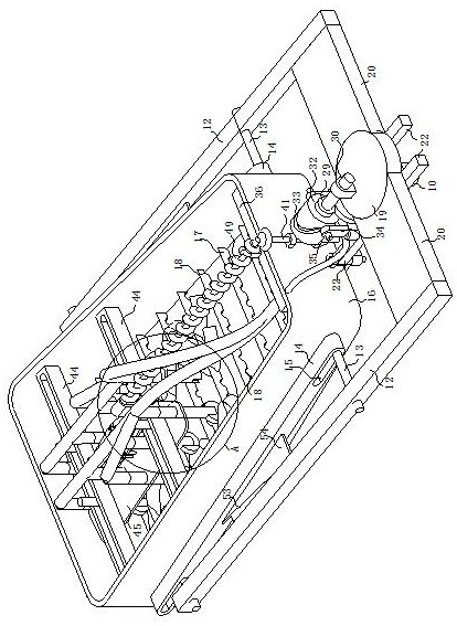
[0038] see Figure 1-10 , the present invention provides a technical solution: a cleaning device for the production of robot parts, including a motor 10, a water pump 11 and two symmetrically arranged fixing frames 12. Slide bar 13, one end of the slide bar 13 on the same side away from the fixed frame 12 is horizontally slidably connected with a fixed bar 14, the side wall of the fixed bar 14 is provided with a plurality of vibration oblong holes 15 corresponding ...


PUM


Abstract

The invention discloses a cleaning device for robot accessory production in the technical field of cleaning for accessory production. The cleaning device comprises a motor, a water pump and two symmetrically arranged fixing frames, wherein two sliding rods are transversely and slidably arranged on the side walls of the two ends of the two fixing frames respectively, fixing rods are horizontally and slidably connected to the ends, away from the fixing frames, of the sliding rods on the same side, a plurality of vibrating long round holes corresponding to the sliding rods are formed in the side walls of the fixing rods, the outer walls of the sliding rods are slidably arranged on the inner walls of the vibrating long round holes, a cleaning tank is fixedly arranged between the two fixing rods, and one end of the cleaning tank is large, and the other end of the cleaning tank is small. The device effectively solves the problems that when existing equipment cleans accessories, ultrasonic waves are usually adopted for exciting a cleaning agent, due to the fact that accessories are different in shape, when cavities exist in the parts, the shocking cleaning agent loses a large amount of energy when touching the surfaces of the parts, and therefore the cleaning agent is difficult to enter the cavities in the parts to conduct efficient cleaning, and therefore the phenomenon of incomplete cleaning is avoided.

Description

technical field [0001] The invention relates to the technical field of cleaning for accessory production, in particular to a cleaning device and method for robot accessory production. Background technique [0002] The production process of accessories requires multiple processes, which are contaminated with dust and other sundries or other processing liquids during the production process, and are easily affected by these sundries when they need to be assembled. Cleaning, which in turn requires the use of accessory cleaning equipment. [0003] Existing equipment usually uses ultrasonic waves to excite the cleaning agent when cleaning the accessories, so that the cleaning agent can obtain the ability to generate vibrations to decontaminate and clean the surface of the parts, but this cleaning method can only clean the stains on the surface of the parts. The shapes are different. When the part has a cavity, the oscillating cleaning agent will lose a lot of energy when it touch...

Claims


Application Information

Patent Timeline
Patent Type & Authority Applications(China)
IPC IPC(8): B08B3/10B08B3/12B08B3/08B08B13/00B24B31/10
CPCB08B3/10B08B3/123B08B3/08B08B13/00B24B31/10
Inventor 葛晓敏
Owner 昂越(上海)机械有限公司
Why Eureka
Eureka Blog
Learn More