Anti-deformation device for warp knitted fabric after forming

A deformation device and warp-knitted fabric technology, which is applied in the field of knitted fabrics, can solve the problems of easy deformation, straight-line fixation of knitted fabrics, and low shaping efficiency of warp-knitted fabrics, and achieve the effects of flexible adjustment and improved shaping efficiency and quality

Active Publication Date: 2021-08-03
广西贺州锐佳塑胶五金制品有限公司
View PDF7 Cites 0 Cited by
  • Summary
  • Abstract
  • Description
  • Claims
  • Application Information

AI Technical Summary

Problems solved by technology

[0006] Aiming at the deficiencies of the prior art, the present invention provides an anti-deformation device for warp knitted fabric after forming, which can quickly linearly fix the edge of the warp knitted fabric, and can adjust the setting support range according to the shape of the warp knitted fabric. Thereby improving the efficiency and quality of warp-knitted fabrics, it solves the problem that traditional warp-knitted fabrics need to be set through a large number of steel wires and T needles, and it is impossible to straightly fix some knitted fabrics that need to be linearly shaped, resulting in warp-knitted fabrics The problem of low efficiency and easy deformation of object setting

Method used


Image

  • Anti-deformation device for warp knitted fabric after forming
  • Anti-deformation device for warp knitted fabric after forming
  • Anti-deformation device for warp knitted fabric after forming

Examples


Embodiment 1

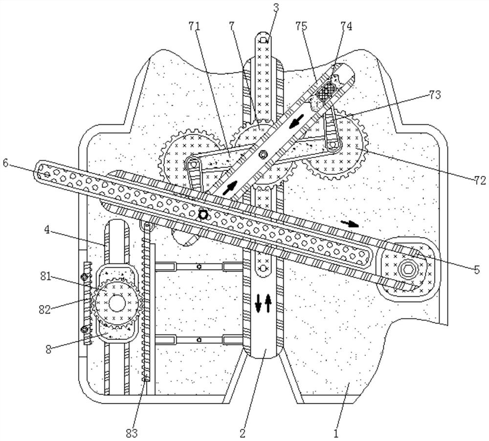
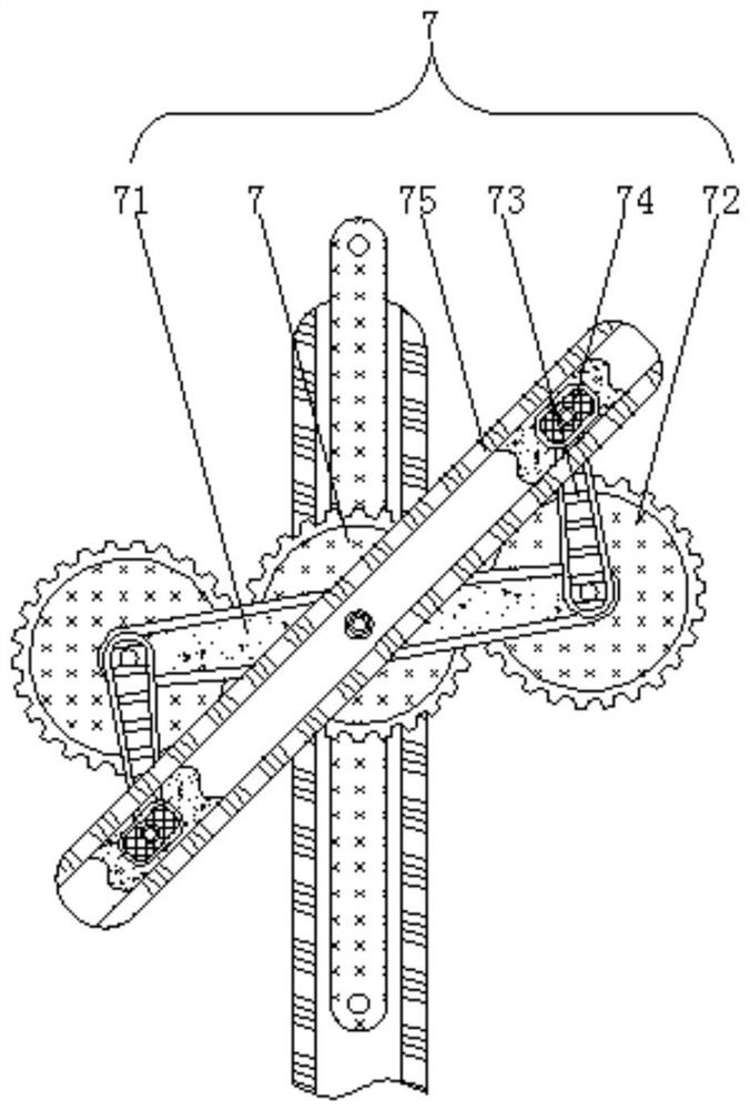
[0026] An anti-deformation device after forming warp knitted fabrics, comprising a driving gear mechanism 7, the driving gear mechanism 7 is rotatably connected to the surface of the driving guide rod 3, two pinion gear mechanisms 72 are provided, and they are respectively rotatably connected to two ends of the connecting rod 71. end, and these two secondary gear mechanisms 72 are meshed with the drive gear mechanism 7, and the front and back sides of the double-sided guide rail 75 are provided with a chute, and the slide block 74 is slidably connected to the back side of the double-sided guide rail 75.

[0027] The shaft center of the drive gear mechanism 7 is rotatably connected with a connecting rod 71, the drive guide rod 3 is arranged at the back axis of the drive gear mechanism 7, the connecting rod 71 is arranged at the front shaft center of the drive gear mechanism 7, and the double-sided guide rail 75 is arranged on the front axle center place of connecting rod 71, and...

Embodiment 2

[0032] An anti-deformation device after forming warp knitted fabrics, comprising a driving gear mechanism 7, the driving gear mechanism 7 is rotatably connected to the surface of the driving guide rod 3, two pinion gear mechanisms 72 are provided, and they are respectively rotatably connected to two ends of the connecting rod 71. end, and these two secondary gear mechanisms 72 are meshed with the drive gear mechanism 7, and the front and back sides of the double-sided guide rail 75 are provided with a chute, and the slide block 74 is slidably connected to the back side of the double-sided guide rail 75.

[0033] The shaft center of the drive gear mechanism 7 is rotatably connected with a connecting rod 71, the drive guide rod 3 is arranged at the back axis of the drive gear mechanism 7, the connecting rod 71 is arranged at the front shaft center of the drive gear mechanism 7, and the double-sided guide rail 75 is arranged on the front axle center place of connecting rod 71, and...

Embodiment 3

[0037] An anti-deformation device after forming warp knitted fabrics, comprising a driving gear mechanism 7, the driving gear mechanism 7 is rotatably connected to the surface of the driving guide rod 3, two pinion gear mechanisms 72 are provided, and they are respectively rotatably connected to two ends of the connecting rod 71. end, and these two secondary gear mechanisms 72 are meshed with the drive gear mechanism 7, and the front and back sides of the double-sided guide rail 75 are provided with a chute, and the slide block 74 is slidably connected to the back side of the double-sided guide rail 75.

[0038] The shaft center of the drive gear mechanism 7 is rotatably connected with a connecting rod 71, the drive guide rod 3 is arranged at the back axis of the drive gear mechanism 7, the connecting rod 71 is arranged at the front shaft center of the drive gear mechanism 7, and the double-sided guide rail 75 is arranged on the front axle center place of connecting rod 71, and...


PUM


Abstract

The invention relates to the technical field of knitted fabrics, and discloses an anti-deformation device for a warp knitted fabric after forming. The device comprises a driving gear mechanism; a connecting rod is rotatably connected to the axis of the driving gear mechanism; an auxiliary gear mechanism is rotatably connected to the end, away from the driving gear mechanism, of the connecting rod; a rotating rod is fixedly connected to the axis of the auxiliary gear mechanism; the surface of the rotating rod is rotationally connected with a sliding block; and the axis of the connecting rod is rotationally connected with a double-face guide rail. According to the anti-deformation device for the warp knitted fabric after forming, a driving guide rod slides along the surface of a first guide rail to drive the driving gear mechanism and the connecting rod to move along with a driving guide rod, and the front face of the double-face guide rail pushes a pulley mechanism arranged on the surface of a supporting rod to drive the supporting rod to slide along the surface of a guide groove, so that the positions of pin fixing holes in the surface of the supporting rod are changed, the linear position of warp knitted fabric shaping can be rapidly adjusted, and shaping of the warp knitted fabric is facilitated.

Description

technical field [0001] The invention relates to the technical field of braided fabrics, in particular to an anti-deformation device after warp knitted fabrics are formed. Background technique [0002] Warp-knitted fabrics are knitted fabrics formed by knitting one or more groups of warp yarns into loops and interlocking on a warp-knitting machine at the same time. Therefore, the structure of the warp knitted fabric is more stable, and the longitudinal and transverse elasticity is also small. Therefore, anti-deformation treatment must be done when aligning and designing a certain shape, otherwise it will be difficult to adjust the later shape due to the stable structure of the warp knitted fabric, which will affect the aesthetics. . [0003] The traditional setting of warp-knitted fabrics made of linen is to wear a circle of steel wires on the outermost edge of the warp-knitted fabrics, and then use T needles to fix the steel wires, so as to prevent the steel wires from bein...

Claims


Application Information

Patent Timeline
Patent Type & Authority Applications(China)
IPC IPC(8): D06C3/00D06C3/10
CPCD06C3/00D06C3/10
Inventor 朱建宁
Owner 广西贺州锐佳塑胶五金制品有限公司
Why Eureka
Try Eureka