Center shaft bowl group structure for electric bicycle

A technology for electric bicycles and group structures, applied in the direction of bearing components, shafts and bearings, vehicle parts, etc., can solve the problems of small rotational friction resistance, bumps on legs and obstacles, etc., and achieve the effect of reliable performance and simple structure

Pending Publication Date: 2021-08-03
TIANJIN XINRI ELECTROMECHANICAL
View PDF6 Cites 0 Cited by
  • Summary
  • Abstract
  • Description
  • Claims
  • Application Information

AI Technical Summary

Problems solved by technology

[0002] The center shaft headsets used in the existing electric bicycles all use metal ball frames or metal bearing structures. Due to the small rotational friction resistance of this structure, there is a disadvantage that the motor drives the flywheel to rotate and transmits to the center shaft crank to rotate with the electric bicycle. The safety risk of causing the crank to rotate at a high speed and hurt the leg or hit an obstacle

Method used


Image

  • Center shaft bowl group structure for electric bicycle
  • Center shaft bowl group structure for electric bicycle
  • Center shaft bowl group structure for electric bicycle

Examples


Embodiment 1

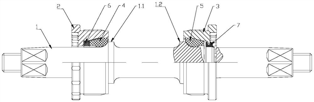
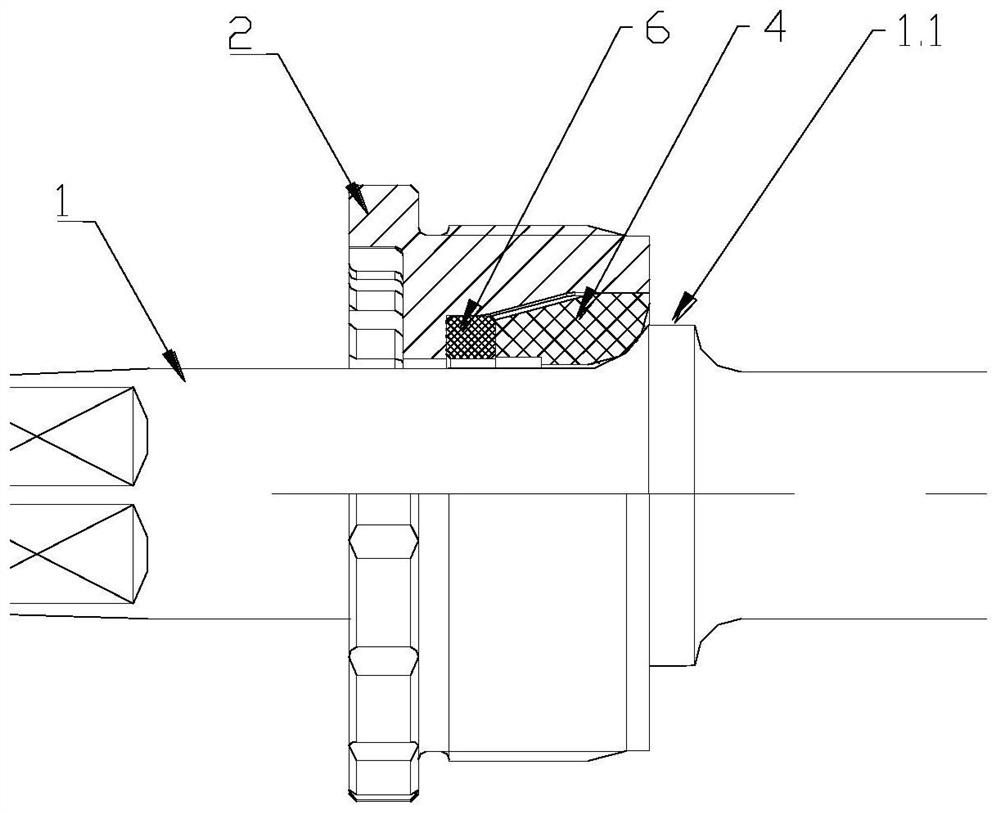
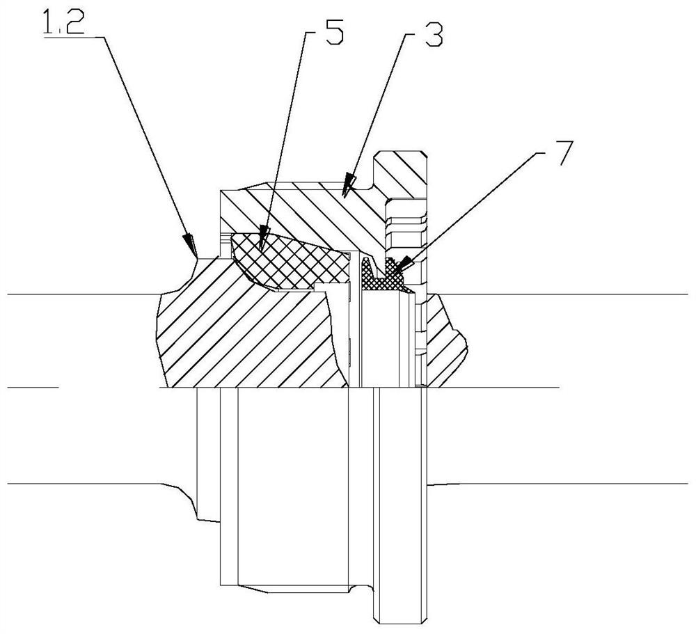
[0032] See attached Figure 1-3 , a center shaft headset structure for an electric bicycle, including a center shaft 1, a positive tooth bowl 2, a negative tooth bowl 3, a first shaft sleeve 4, a second shaft sleeve 5 and a buffer washer 6.

[0033] The central axis 1 is provided with two limiting flanges 1.1 and 1.2, which are arranged along the circumferential direction of the central axis. The height of the limiting flanges is preferably 5-10 mm. Between the two limiting flanges The axial distance is preferably 6-12cm. The outer surface of the limiting flange is an arc-shaped concave structure (the outer surface of the limiting flange refers to the side of the limiting flange facing the outer end of the central axis), and the roughness of the arc-shaped concave surface is preferably 0.4-1.2; The shape of the inner surface of the limiting flange is not limited, and it can be a shape such as a slope or an arc (the inner surface of the limiting flange refers to the side of th...

Embodiment 2

[0040] On the basis of Embodiment 1, further speaking, another buffer washer may be provided at the inner end of the second shaft sleeve to increase the elastic compensation effect.

Embodiment 3

[0042] On the basis of Embodiment 1, further speaking, a sealing ring 7 is provided on the outer end of the orthodontic bowl and / or the inverse tooth bowl.


PUM


Abstract

The invention discloses a center shaft bowl group structure for an electric bicycle.Two limiting flanges are arranged on a center shaft, and the outer side faces of the limiting flanges are of arc-shaped concave face structures. The inner edges of the outer end faces of a first shaft sleeve and a second shaft sleeve are of arc-shaped convex face structures, the middle shaft is sleeved with the two shaft sleeves which are located in the forward tooth bowl installation cavity and the reverse tooth bowl installation cavity respectively, and the arc-shaped convex faces of the two shaft sleeves make contact with the arc-shaped concave faces on the outer side of the limiting flanges on the middle shaft and are matched with the arc-shaped concave faces in a sliding contact mode. An elastic buffering piece is located at the inner end of the first shaft sleeve and/or the second shaft sleeve. Due to the fact that the shaft sleeves and the limiting flanges of the center shaft are in sliding fit with a large contact surface, certain friction resistance can be generated when the shaft sleeves and the limiting flanges of the center shaft rotate relatively, and due to the existence of the elastic buffering piece, the effect of automatic displacement compensation of friction loss of the shaft sleeves can be achieved, and generated friction force attenuation is slow, so that the problem that the motor of the electric bicycle drives a flywheel to rotate and drives a center shaft crank to rotate together is solved.

Description

technical field [0001] The invention belongs to the technical field of electric bicycles, and in particular relates to a center shaft headset structure for electric bicycles. Background technique [0002] The center shaft headsets used in the existing electric bicycles all use metal ball frames or metal bearing structures. Due to the small rotational friction resistance of this structure, there is a disadvantage that the motor drives the flywheel to rotate and transmits to the center shaft crank to rotate with the electric bicycle. The safety risk of causing the crank to rotate at high speed to hurt the legs or bump into obstacles. Contents of the invention [0003] The object of the present invention is to overcome the deficiencies of the prior art and provide a center shaft headset structure for an electric bicycle. [0004] The present invention is achieved through the following technical solutions: [0005] A center shaft headset structure for an electric bicycle, co...

Claims


Application Information

Patent Timeline
Patent Type & Authority Applications(China)
IPC IPC(8): F16C35/10B62M6/40
CPCF16C35/10B62M6/40
Inventor 罗明建裴明明娄海明
Owner TIANJIN XINRI ELECTROMECHANICAL
Why Eureka
Try Eureka