Vacuum water-cooling rotary joint

A rotary joint, vacuum water cooling technology, applied in the direction of pipe/pipe joint/pipe fitting, adjustable connection, pipeline heating/cooling, etc., can solve the problem of unused, achieve convenient installation and debugging, solve the follow-up problem, good cooling effect of effect

Active Publication Date: 2015-04-15
WISDRI ENG & RES INC LTD
View PDF7 Cites 0 Cited by
  • Summary
  • Abstract
  • Description
  • Claims
  • Application Information

AI Technical Summary

Problems solved by technology

Because of these stringent requirements, the arrangement of the dynamic method on the domestic vacuum chamber is hardly used

Method used


Image

  • Vacuum water-cooling rotary joint
  • Vacuum water-cooling rotary joint
  • Vacuum water-cooling rotary joint

Examples


Embodiment Construction

[0029] Below in conjunction with specific embodiment, the present invention is further described:

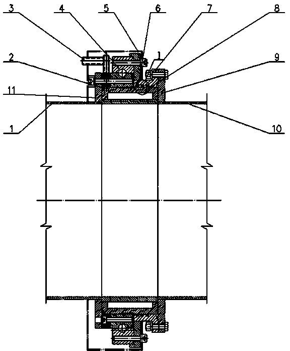
[0030] Such as figure 1 The vacuum water-cooled rotary joint shown includes a left flange 11 and a right flange 9 connected to the vacuum pumping pipe, and a water-cooled core 8 is installed between the two flanges close to the pipe, and the water-cooled core 8 wraps the circumference of the pipe in a ring shape. A cooling water pipe 3 is provided on the water-cooling inner core 8, and an annular slewing bearing 4 is arranged on the outer side of the water-cooling inner core 8. The slewing bearing 4 is divided into two layers, an inner ring and an outer ring, and can rotate with each other. The left flange 11 is provided with There are bolt holes 17, the water-cooling core 8 is connected with the left flange 11 and the inner ring of the slewing bearing 4 through a bolt group, the water-cooling core 8 is also provided with an annular jacket 7, and the jacket 7 is connected with t...


PUM


Abstract

The invention provides a vacuum water-cooling rotary joint for a vacuum extraction pipe under the condition of large size, high temperature and vacuum negative pressure in the RH vacuum molten-steel treatment process. The vacuum water-cooling rotary joint comprises a left flange and a right flange which are connected with the vacuum extraction pipe, wherein a water-cooling inner core is arranged at the position between the two flanges close to the pipeline, and is ring-shaped to wrap the periphery of the pipeline; the water-cooling inner core is provided with a cooling water pipe; the outer side of the water-cooling inner core is provided with a ring-shaped rotary support; the rotary support comprises an inner ring and an outer ring which can rotate mutually; the water-cooling inner core is connected with the left flange and the inner ring of the rotary support by a bolt group, and is also externally provided with a ring-shaped outer sleeve; and the outer sleeve is connected with the right flange and the outer ring of the rotary support by anthe other group of bolts. The vacuum water-cooling rotary joint provided by the invention is convenient in installation and debugging, can adapt to the environment with large-size extraction pipes, the extremely-high-temperature flue gas and vacuum negative pressure and solves the following problem of the vacuum extraction pipe.

Description

technical field [0001] The invention belongs to the field of equipment in the metallurgical industry, and in particular relates to a vacuum water-cooled rotary joint for a large-sized, high-temperature, vacuum suction pipe under vacuum negative pressure, which is used in the RH vacuum molten steel treatment process. Background technique [0002] In the steelmaking RH vacuum degassing process, in order to improve the quality of steel tapping and achieve the purpose of secondary refining, the vacuum pumping system must ensure good air tightness. The vacuum exhaust pipe is an airtight pipe arranged between the vacuum chamber and the vacuum pump system, with a diameter of usually 1200mm to 2200mm, the ultimate negative pressure inside the pipe is 28Pa, and the temperature of the flue gas in the pipe is as high as nearly 1000°C. At present, the layout of the RH vacuum system has two ways: the vacuum chamber up-moving type and the ladle down-moving type. The ladle moves downward,...

Claims


Application Information

Patent Timeline
Patent Type & Authority Patents(China)
IPC IPC(8): F16L27/08F16L53/00
Inventor 黄俊刘斌奇李智宋晓燕许海虹张文张钟蓓张愉汪龙廖坤明
Owner WISDRI ENG & RES INC LTD
Why Eureka
Try Eureka