
Three-dimensional reconstruction method for light field of high-reflection surface structure based on point cloud self-adaptive repair

An adaptive repair and 3D reconstruction technology, applied in the field of 3D reconstruction of objects with highly reflective areas, can solve the problems of 3D model data holes, inability to have large areas of high reflectivity, limited reflectivity, etc. Reconstruction effect and precision, effect to improve accuracy and believability

Active Publication Date: 2021-08-03
HUBEI UNIV OF TECH
View PDF9 Cites 8 Cited by
  • Summary
  • Abstract
  • Description
  • Claims
  • Application Information

AI Technical Summary

Problems solved by technology

The traditional optical three-dimensional measurement technology is limited to a certain extent by the reflectivity of the surface of the measured object, and it is required that there should be no large areas of high reflectivity on the surface of the measured object.
However, in the industrial application process, the surface of the part will become very bright after processing. When using traditional optical three-dimensional measurement technology to measure the part, it is necessary to collect the part image through the camera. Due to the high reflectivity of the part surface, it will cause There are large areas of overexposure in the collected images, which leads to large data holes in the reconstructed 3D model of the part

Method used


Image

  • Three-dimensional reconstruction method for light field of high-reflection surface structure based on point cloud self-adaptive repair
  • Three-dimensional reconstruction method for light field of high-reflection surface structure based on point cloud self-adaptive repair
  • Three-dimensional reconstruction method for light field of high-reflection surface structure based on point cloud self-adaptive repair

Examples


Embodiment Construction

[0058] The technical solutions of the present invention will be further described below in conjunction with the accompanying drawings and embodiments.

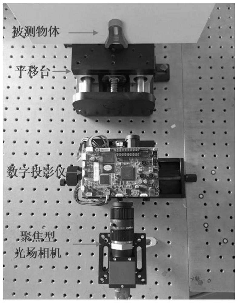
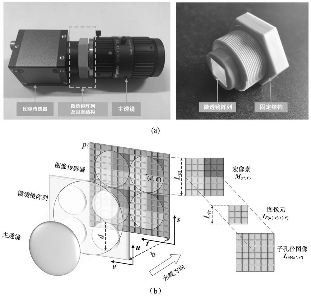
[0059] The invention discloses a method for three-dimensional reconstruction of highly reflective surface structure light field based on point cloud self-adaptive repair and a corresponding reconstruction system evaluation method; and proposes a sub-aperture image extraction method based on image mosaic for a focused light field camera . Light field imaging technology can record the position information and direction information of light at the same time. Therefore, compared with traditional cameras, light field cameras can capture four-dimensional light field information. By extracting four-dimensional light field information, a multi-view image of the scene can be obtained. Aperture images, and due to different viewing angles, there is a certain complementarity in the stored information between the sub-aperture images. Ligh...


PUM


Abstract

The invention discloses a three-dimensional reconstruction method for a light field of a high-reflection surface structure based on point cloud self-adaptive repair. The method comprises the following steps: firstly, building a structured light field three-dimensional reconstruction system, and extracting a multi-view light field sub-aperture image; then, calibrating the reconstruction systemcalibrating , projecting the sine stripe sequence projecting to a reference plane, moving the reference planemoving, recording phase changes recordingon the reference plane under each moving distance through a focusing type light field camera, and subtracting the phase changes from phase values of pixel points at an initial position to obtain a phase difference-depth-of-field (moving distance) mapping relation; reconstructing to obtain a multi-view three-dimensional point cloud through a sub-aperture image extraction algorithm and a mapping relation; and finally, multi-view point cloud data obtained through reconstruction having certain complementarity. A data cavity part in the target point cloud can be iteratively repaired by the same position of other view point clouds, so that complete three-dimensional reconstruction of a high-reflective surface object is realized. In addition, aiming at the reconstruction result, the invention provides a corresponding evaluation method.

Description

technical field [0001] The invention relates to a three-dimensional reconstruction method, in particular to a three-dimensional reconstruction method for an object with a highly reflective area. Background technique [0002] Optical 3D measurement methods have the advantages of full-field acquisition, non-contact, low cost, high precision, and fast processing, and have been widely used in academic research and industrial fields. The traditional optical three-dimensional measurement technology is limited to a certain extent by the reflectivity of the surface of the measured object, and it is required that there should be no large areas of high reflectivity on the surface of the measured object. However, in the industrial application process, the surface of the part will become very bright after processing. When using traditional optical three-dimensional measurement technology to measure the part, it is necessary to collect the part image through the camera. Due to the high r...

Claims


Application Information

Patent Timeline
Patent Type & Authority Applications(China)
IPC IPC(8): G06T17/00G06T7/80G06T7/62G06T7/30G06T7/00G06T3/40
CPCG06T17/00G06T7/85G06T7/62G06T7/30G06T7/0004G06T3/4038G06T2207/10028G06T2207/30164
Inventor 冯维曲通高俊辉程雄昊周世奇祝振敏张福民赵大兴
Owner HUBEI UNIV OF TECH
Learn More