Fuel cell stack with stress-adjustable end plates

A fuel cell stack, an adjustable technology, applied in the directions of fuel cells, circuits, electrical components, etc., can solve the problems of inability to adjust the assembly force of the fuel cell, the size of the force is not equal, and prevent the stack from being poorly sealed. The effect of prolonging the life and preventing the leakage of the reaction gas

Inactive Publication Date: 2021-08-03
胡定良
View PDF0 Cites 6 Cited by
  • Summary
  • Abstract
  • Description
  • Claims
  • Application Information

AI Technical Summary

Problems solved by technology

[0005] The purpose of the present invention is to provide a fuel cell stack with adjustable force on the end plate, to solve the problem that the force on each point between the bipolar plates in the fuel cell in the prior art is not equal, and the inside of the fuel cell cannot be adjusted during use. Technical Problems in Adjusting Assembly Force

Method used


Image

  • Fuel cell stack with stress-adjustable end plates
  • Fuel cell stack with stress-adjustable end plates
  • Fuel cell stack with stress-adjustable end plates

Examples


Embodiment 2

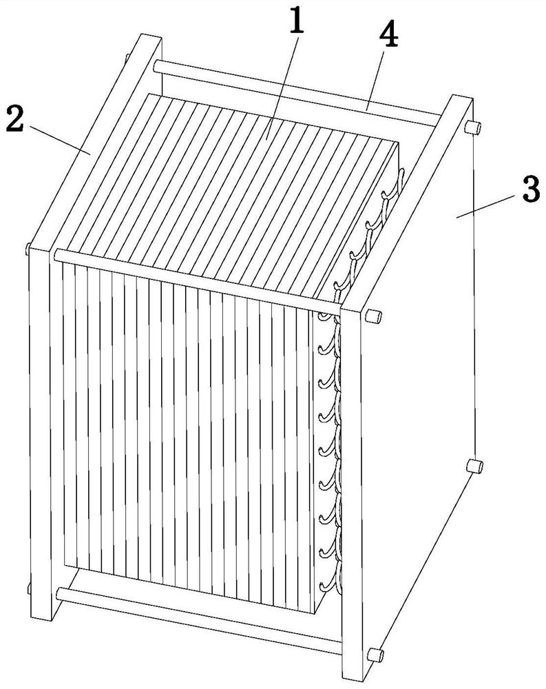
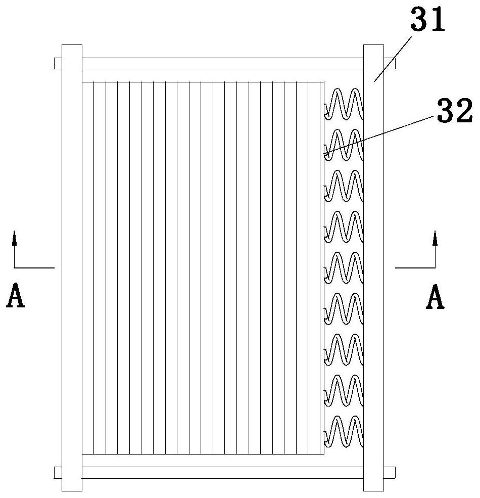
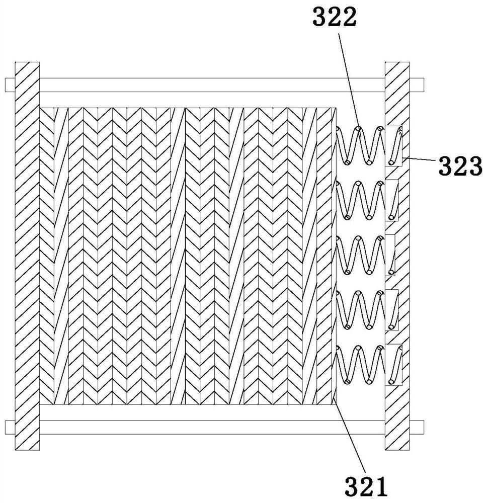
[0041] combine Figure 4-6 As shown, the present invention provides a fuel cell stack with adjustable end plate force, including a stack mechanism 1, and the two ends of the stack mechanism 1 are respectively provided with a fixed end plate 2 and an adjustable end plate mechanism 3, The adjustment end plate mechanism 3 includes an adjustment end plate 31 and an adjustment assembly 32 matched with the adjustment end plate 31, the adjustment assembly 32 is located between the adjustment end plate 31 and the stack mechanism 1, the fixed end plate 2 and the adjustment There are several fixed rods 4 for connecting the two end plates 31, and the two ends of each fixed rod 4 are respectively connected with the fixed end plate 2 and the adjustment end plate 31 by bolts; the adjustment assembly 32 includes a spring end Plate 321 , one side of the spring end plate 321 is fixedly connected with the electric stack mechanism 1 , and the adjusting end plate mechanism 3 is used to provide th...

Embodiment 3

[0047] combine Figure 7-Figure 9 As shown, the present invention provides a fuel cell stack with adjustable end plate force, including a stack mechanism 1, and the two ends of the stack mechanism 1 are respectively provided with a fixed end plate 2 and an adjustable end plate mechanism 3, The adjustment end plate mechanism 3 includes an adjustment end plate 31 and an adjustment assembly 32 matched with the adjustment end plate 31, the adjustment assembly 32 is located between the adjustment end plate 31 and the stack mechanism 1, the fixed end plate 2 and the adjustment There are several fixed rods 4 for connecting the two end plates 31, and the two ends of each fixed rod 4 are respectively connected with the fixed end plate 2 and the adjustment end plate 31 by bolts; the adjustment assembly 32 includes a spring end Plate 321 , one side of the spring end plate 321 is fixedly connected with the electric stack mechanism 1 , and the adjusting end plate mechanism 3 is used to pro...


PUM


Abstract

The invention discloses a fuel cell stack with stress-adjustable end plates, and relates to the technical field of fuel cells. The fuel cell stack comprises a stack mechanism, two ends of the stack mechanism are respectively provided with a fixed end plate and an adjusting end plate mechanism, and the adjusting end plate mechanism comprises an adjusting end plate and an adjusting assembly matched with the adjusting end plate. The adjusting assembly is located between the adjusting end plate and the galvanic pile mechanism, the adjusting assembly comprises a spring end plate, one side of the spring end plate is fixedly connected with the galvanic pile mechanism, and the adjusting end plate mechanism provides pressure which is gradually reduced from the center of the spring end plate to the periphery for the galvanic pile mechanism. According to the invention, the adjusting assembly works to enable the stress of each point in the stack to be the same, so that the stack structure design of the fuel cell is more perfected, an overlarge initial assembly gap between the polar plate and the MEA can be avoided, and a relatively poor stack sealing effect and reaction gas leakage can also be prevented from causing more serious consequences; the performance, the quality and the service life of the fuel cell are improved, and the potential safety hazard during use of the fuel cell is reduced.

Description

technical field [0001] The invention relates to the technical field of fuel cells, in particular to a fuel cell stack with adjustable stress on end plates. Background technique [0002] The fuel cell stack is assembled by a number of identical single cells in series, mainly including end plates, bipolar plates, membrane electrodes, sealing gaskets and other components, in which each single cell receives assembly pressure under the action of fastening bolts on the end plates , the bipolar plate is a statically indeterminate assembly between the MEA. Gan Frequency and others pointed out in "Distribution Law of Metal Plate Fuel Cell Stack Contact Pressure" that the transfer mechanism of the internal assembly pressure of the stack is: after the torque is applied, the end plate generates an assembly force on the metal plate, and the metal plate Under the action of assembly force, the compression gasket reduces its thickness and makes contact with the MEA. Therefore, after the a...

Claims


Application Information

Patent Timeline
Patent Type & Authority Applications(China)
IPC IPC(8): H01M8/247H01M8/248
CPCH01M8/247H01M8/248Y02E60/50
Inventor 胡定良
Owner 胡定良
Why Eureka
Try Eureka