Boring device, boring method and stern shaft installation method

A technology of boring and stern tube, which is applied in the field of ship shafting installation, can solve the problems of easy bending and deformation of boring bars, low precision, poor quality of boring holes, etc. Effect

Active Publication Date: 2022-07-19
中石化石油工程技术服务有限公司 +1
View PDF0 Cites 0 Cited by
  • Summary
  • Abstract
  • Description
  • Claims
  • Application Information

AI Technical Summary

Problems solved by technology

[0003] Aiming at the deficiencies of the prior art, the technical problem to be solved by the present invention is that the existing boring bar is easily bent and deformed when boring horizontally, and the central axis of the boring bar cannot be aligned with the theoretical center of the shaft system, resulting in poor boring quality and low precision. The boring operation cannot be carried out on the platform of the stern tube general section, so the shafting cannot be installed in advance, which affects the construction period

Method used


Image

  • Boring device, boring method and stern shaft installation method
  • Boring device, boring method and stern shaft installation method
  • Boring device, boring method and stern shaft installation method

Examples


no. 2 example

[0097] Please also refer to Figure 8 , the present embodiment provides a boring method S10 for using the boring device 1 to bore the stern tube 10, including the following steps:

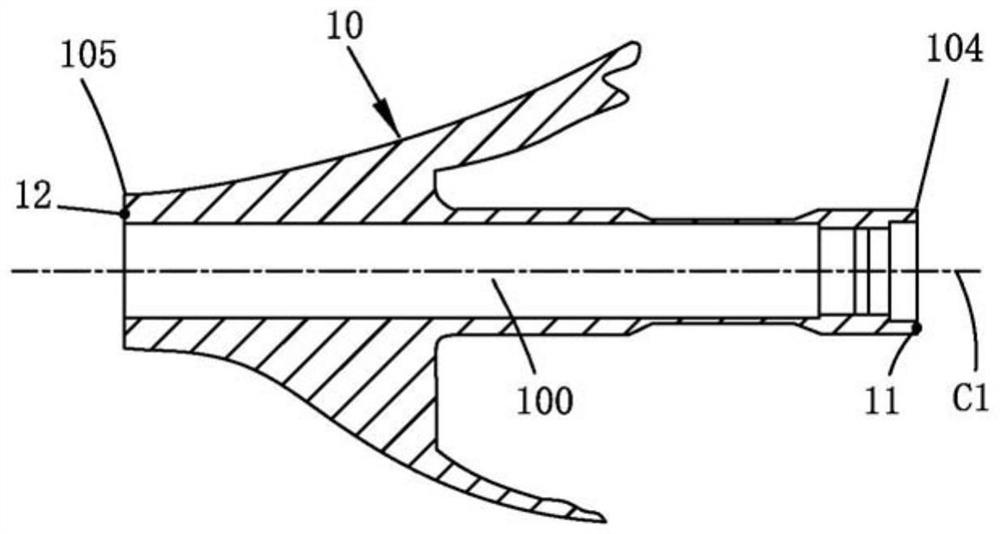
[0098] S100: as image 3 As shown, the light target bow base point 11 and the light target stern base point 12 are set, and the theoretical centerline C1 of the shaft system is determined by illumination. Light targets are respectively set at the base point 11 of the light target bow and the base point 12 of the light target stern, and the light target at the base point 11 of the light target bow and the light target at the base point 12 of the light target stern are illuminated by the light source, and the line segment passing through the center of the two light targets is the axis system Theoretical centerline C1. After the theoretical centerline C1 of the shaft system is determined, the position and angle of the light source need to be kept fixed for subsequent reference point determination. ...

no. 3 example

[0114] Please also refer to Figure 5 and Figure 12 , this embodiment provides a stern shaft installation method, using the aforementioned boring device 1, including the following steps:

[0115] S200: Construction of the overall stern tube section.

[0116] S202: Use the boring method S10 for boring.

[0117] S203 : Press the bearing bush into the fifth through hole 103 . Pressing the bearing bushing requires a single press into place. Before pressing the bearing bushing, the bearing bushing needs to be cooled, so that the bearing bushing forms an interference fit with the fifth through hole 103 during operation. For example, bearing bushing cooling can be done with liquid nitrogen ice, which allows the bearing bushing to shrink before being press-fitted. In order to avoid the bearing bushing being scrapped after installation, it is required to press the bearing bushing in place at one time. If the bearing bushing is not pressed in place or pulled out again, the bearing...


PUM


Abstract

The invention provides a boring device, a boring method and a stern shaft installation method. The boring device is used for boring a stern shaft tube. The boring device comprises: a light target bow base point, a light target bow base point, a boring bar , a positioning device, a first support frame, a support body and a second support frame. The stern shaft installation method includes: constructing a general section of the stern shaft tube, using a boring device for boring, pressing the bearing bushing to the fifth through hole, inserting the stern shaft into the bearing sleeve and the fifth through hole, and inserting the propeller into the fifth through hole. Mounted to one end of the stern shaft. The invention solves the problem that the existing boring bar is easy to bend and deform during horizontal boring, the central axis of the boring bar cannot be aligned with the theoretical center of the shaft system, resulting in poor boring quality and low precision, and the existing boring operation cannot be performed in the stern tube general section. Due to the platform progress, the shaft system cannot be installed in advance, which affects the construction period.

Description

technical field [0001] The invention relates to a ship shafting installation method, in particular to a boring device, a boring method and a stern shaft installation method. Background technique [0002] Ship is a large-scale machine, tube, electricity and instrument product integrating high and new technology. Shortening the construction period of the ship in the dock is an extremely important means for ship enterprises to shorten the construction period of the ship. Due to the irreversibility of machining, the axis line formed after the stern tube of the ship is bored is the actual center line of the ship's shafting. All are based on the actual centerline of the shaft system, so the boring accuracy of the stern tube is very important. The inventor found in the research: 1) When boring the stern tube of the ship in the dock stage, the boring row is generally placed horizontally to carry out the boring. Since the boring bar is generally long, the self-gravity of the boring ...

Claims


Application Information

Patent Timeline
Patent Type & Authority Patents(China)
IPC IPC(8): B23B41/00B23B35/00
CPCB23B41/00B23B35/00
Inventor 曹丕廷沈春华贾治平王镪
Owner 中石化石油工程技术服务有限公司
Why Eureka
Try Eureka