
a composite beam

A composite beam and wing plate technology, applied in the field of composite beams, can solve problems such as excessive bending deformation and easy bending deformation, and achieve the effect of preventing deformation and improving bearing capacity

Active Publication Date: 2021-11-02
NORTH CHINA UNIV OF WATER RESOURCES & ELECTRIC POWER
View PDF0 Cites 0 Cited by
  • Summary
  • Abstract
  • Description
  • Claims
  • Application Information

AI Technical Summary

Problems solved by technology

[0004] In order to solve the problem that the beam is easily bent and deformed under a large load during use, the present invention provides a composite beam, which can provide better protection for the beam and avoid excessive bending deformation of the beam

Method used


Image

  • a composite beam
  • a composite beam
  • a composite beam

Examples


Embodiment Construction

[0031] The present invention will be further described below in conjunction with accompanying drawing and specific embodiment:

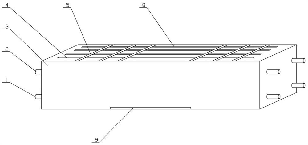
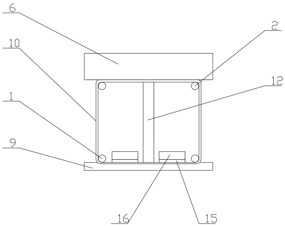
[0032] Such as Figure 1 to Figure 8 As shown, a composite beam includes a composite skeleton;

[0033] The composite skeleton includes a first skeleton, a second skeleton, a third skeleton and an anchor plate, the first skeleton includes a lower wing plate 9, a web 12 and an upper wing plate 11, and the lower wing plate 9 is horizontally arranged Rectangular plate body, described web 12 is the plate body that the lower end of described vertical setting is straight face, and upper end is the curved surface of downward depression, and the lower end of described web 12 is fixed on the center line of top surface of lower wing plate 9, so The upper wing plate 11 is installed on the arc surface of the upper end of the web plate 12. The upper wing plate 11 is an arc-shaped plate body with arc-shaped edges at the front and rear ends, straight edges at the ...


PUM


Abstract

The invention relates to a composite beam, comprising a composite skeleton and a concrete pouring material; the composite skeleton includes a first skeleton, a second skeleton, a third skeleton and an anchor plate, the first skeleton includes a lower wing plate and an upper wing plate, The top surface of the upper wing plate is provided with multiple rows of circular through holes passing through the upper and lower sides of the upper wing plate at intervals along the width direction of the upper wing plate, and vertical first vertical holes are arranged between each adjacent two rows of circular through holes. The ribs, the second frame includes a left frame body and a right frame body with the same structural size, the third frame is a rectangular steel frame, and the third frame includes stirrups and two sets of upright bars. The anchor plates include two groups of anchor plates, front and rear, which are movably installed on the front and rear sides of the web and have the same structural size. In order to solve the problem that the beam is easily bent and deformed under a large load during use, the invention provides a composite beam, which can provide better protection for the beam and avoid excessive bending deformation of the beam.

Description

technical field [0001] The invention relates to the technical field of construction, in particular to a composite beam. Background technique [0002] The beam is supported by the support, and the external force it bears is mainly lateral force and shear force, and the bending is the main deformation component. The beam supports the entire weight of the components in the upper frame of the building and the roof. For important parts, there are shaped steel beams, reinforced concrete beams, wooden beams, steel-clad concrete beams, etc. commonly used in engineering. [0003] The beam is bent and deformed under the action of vertical load. One side of the beam is under tension and the other side is under compression, so the beam is easy to bend and deform during use. The bending deformation of the beam is mainly affected by the load and the structure of the beam. In addition, the beam Generally, it is a long strip structure. Longer beams are more likely to be bent and deformed. ...

Claims


Application Information

Patent Timeline
Patent Type & Authority Patents(China)
IPC IPC(8): E04C5/06E04C3/293
CPCE04C3/293E04C5/065
Inventor 姚贤华
Owner NORTH CHINA UNIV OF WATER RESOURCES & ELECTRIC POWER
Learn More