Cutting tool having high toughness and abrasion resistance

a cutting tool and high toughness technology, applied in the direction of superimposed coating process, other chemical processes, instruments, etc., can solve the problems of low toughness of the coated cutting tool, drastically decreasing and reducing the life of the tool. , to achieve the effect of inhibiting chipping and flaking, high toughness

Active Publication Date: 2010-04-06
KORLOY
View PDF9 Cites 23 Cited by
  • Summary
  • Abstract
  • Description
  • Claims
  • Application Information

AI Technical Summary

Benefits of technology

[0014]Accordingly, the present invention has been made keeping in mind the above problems occurring in the prior art, and an object of the present invention is to provide a cutting tool having high toughness while inhibiting chipping and flaking, comprising a coated cutting tool composed of a cemented carbide substrate, a cermet substrate or a ceramic substrate coated with a hard coating film by means of CVD, MT-CVD or PVD, subjected to wet blasting in which the residual stress of several layers of the coating film of the coated cutting tool is changed from tensile stress to compressive stress, or the residual tensile stress is decreased or the residual compressive stress is increased, thus enhancing the toughness of the coated cutting tool, and also, the surface roughness of an outer layer or an outermost layer of the coating film of the coated cutting tool is reduced, thus inhibiting flaking and chipping of the coating film.
[0015]Another object of the present invention is to provide a cutting tool having high toughness while inhibiting chipping, comprising a cemented cutting tool, a cermet cutting tool, or a ceramic cutting tool, subjected to wet blasting to change residual stress on the cutting tool from tensile stress to compressive stress or increase residual compressive stress, thus increasing the toughness of the cutting tool, and also, the surface roughness of the cutting tool is reduced, thus inhibiting chipping.
[0016]A further object of the present invention is to provide a cutting tool having excellent cutting performance for steel, stainless steel, or cast iron including general cast iron and ductile case iron.
[0017]In order to accomplish the above objects, the present invention provides a cutting tool having high toughness and abrasion resistance, comprising a substrate selected from among a cemented carbide substrate, a cermet substrate and a ceramic substrate and a hard coating film deposited on the substrate by means of a vapor deposition process selected from among chemical vapor deposition, moderate temperature-chemical vapor deposition and physical vapor deposition, and subjected to wet blasting using 10-300 μm sized particles to decrease residual tensile stress or increase residual compressive stress and reduce surface roughness.
[0020]In addition, the present invention provides a cutting tool having high toughness and abrasion resistance, comprising a cutting tool selected from among a cemented carbide cutting tool, a cermet cutting tool and a ceramic cutting tool, subjected to wet blasting using 10-300 μm sized particles to decrease residual tensile stress or increase residual compressive stress and reduce surface roughness.

Problems solved by technology

Further, the coating on the coated cutting tool intended to enhance cutting performance may chip away or flake away.
However, since residual tensile stress attributed to the difference in heat expansion coefficients between the substrate and the film is present on the film, the coated tool has low toughness.
Moreover, the coated tool is disadvantageous because chipping, which causes the film to partially chip away when used for cutting, takes place or the film may be wholly detached from the substrate, thus drastically decreasing the lifetime of the tool.
However, the above invention is disadvantageous because the coating film subjected to both wet blasting and heat treatment has surface roughness inferior to the coating film subjected to only wet blasting.
However, the change of the residual stress on the film exposed along the cutting edge is too low to increase the toughness of the tool, and also, limitations are imposed on the uniform removal of only the top several layers of the cutting edge.
However, the coated cutting tool subjected to dry blasting has surface roughness inferior to cutting tools subjected to wet blasting, and also, the residual stress present on the coating film thereof is extremely high, thus the coated cutting tool is easily breakable.

Method used


Image

  • Cutting tool having high toughness and abrasion resistance
  • Cutting tool having high toughness and abrasion resistance
  • Cutting tool having high toughness and abrasion resistance

Examples


example 1

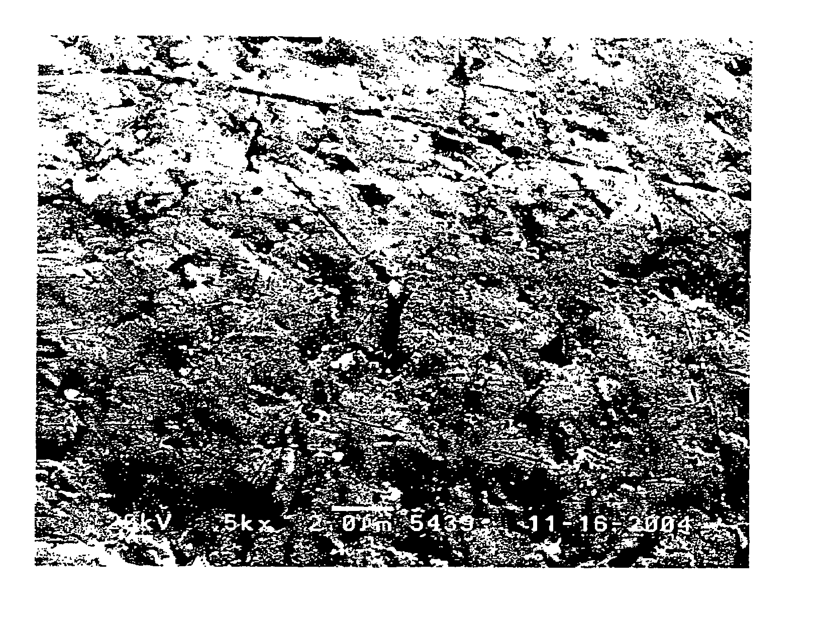
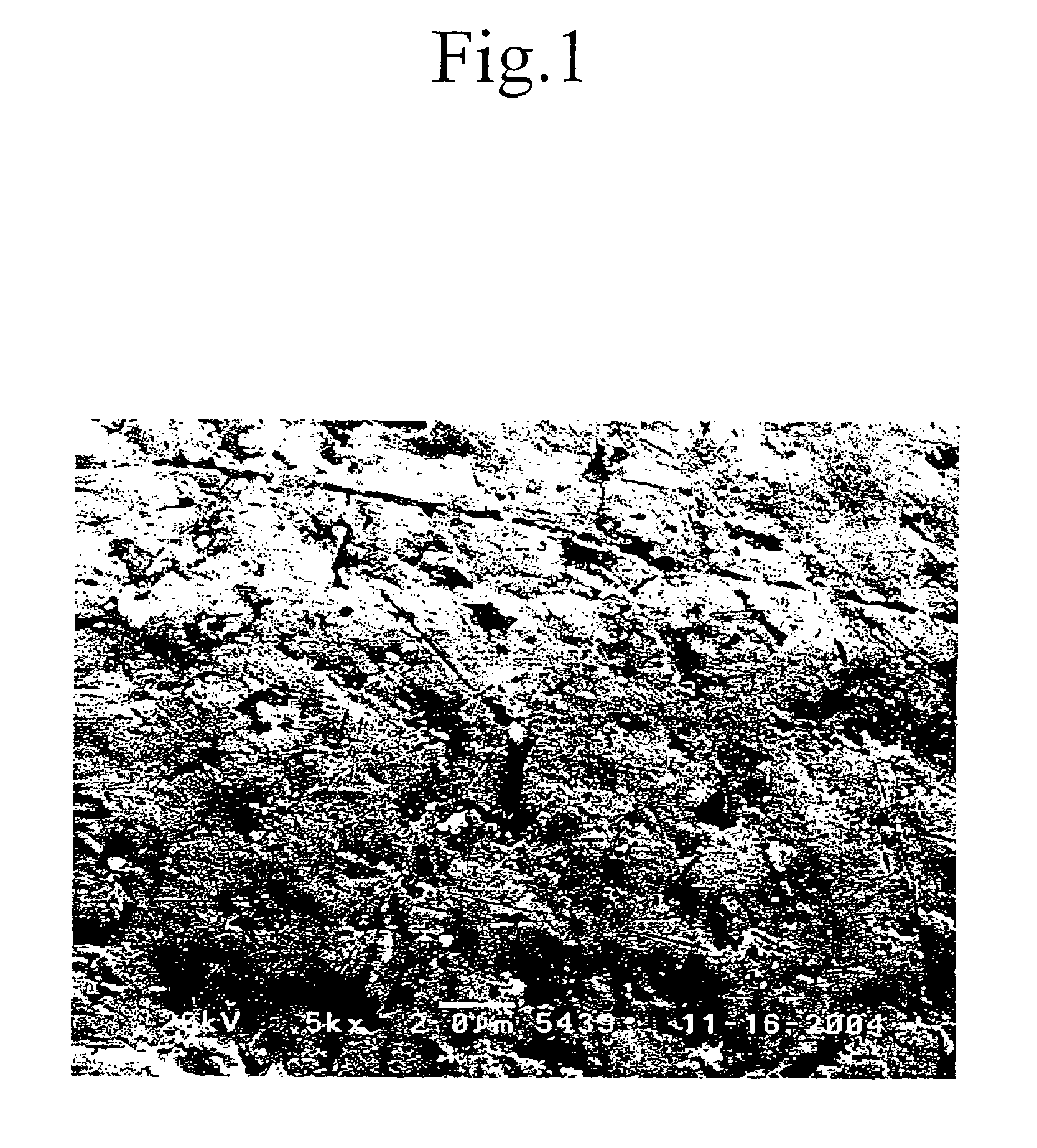
[0028](A) On a cemented carbide substrate for use in a coated cutting tool, corresponding to a grade of ISO K10, a 10.0 μm thick TiCN film, a 5.0 μm thick α-Al2O3 film, and a 1.0 μm thick TiN film were sequentially deposited by means of MT-CVD, to obtain a coated cutting tool.

[0029]The resultant coated cutting tool was subjected to wet blasting using 10-300 μm sized alumina (Al2O3) particles at a pressure of 0.5-5.0 bar.

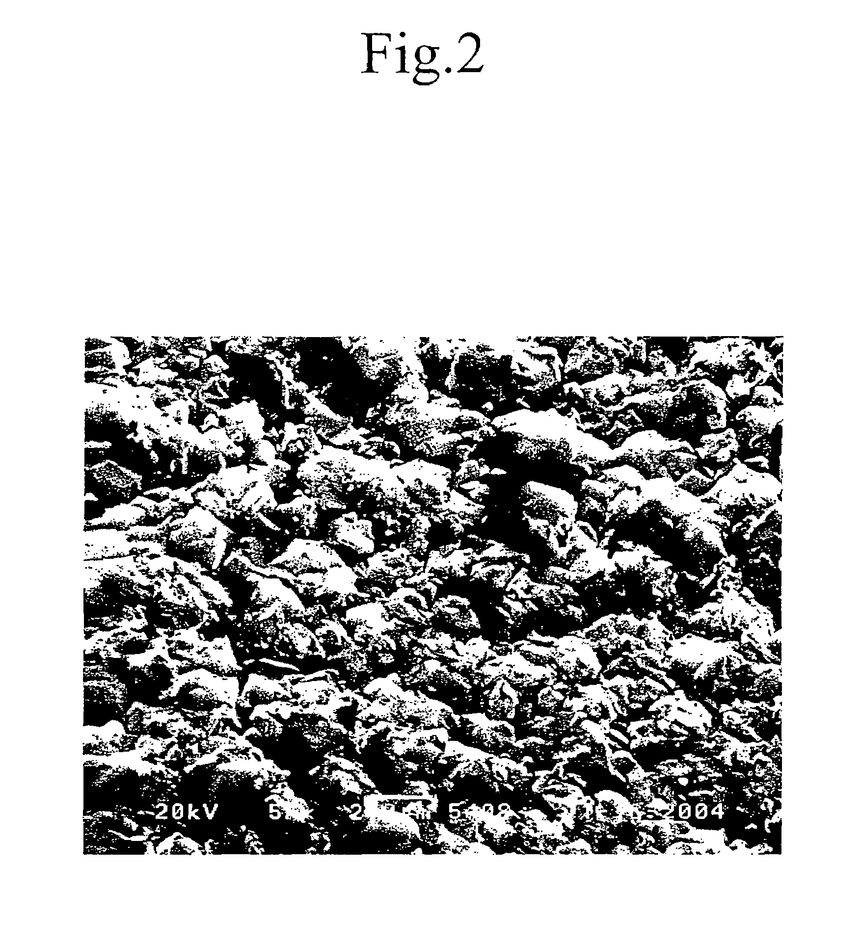
[0030](B) On a cemented carbide substrate for use in a coated cutting tool, corresponding to a grade of ISO K10, a 10.0 μm thick TiCN film, a 5.0 μm thick α-Al2O3 film, and a 1.0 μm thick TiN film were sequentially deposited by means of MT-CVD, to obtain a coated cutting tool.

[0031](C) On a cemented carbide substrate for use in a coated cutting tool, corresponding to a grade of ISO K10, a 10.0 μm thick TiCN film, a 5.0 μm thick α-Al2O3 film, and a 1.0 μm thick TiN film were sequentially deposited by means of MT-CVD, to obtain a coated cutting tool.

[0032]The resultant...

example 2

[0038]Abrasion resistance of the cutting tools manufactured as in Example 1 was measured. To this end, the same workpiece was processed for 20 min, and an abrasion amount generated on a flank of the tool was measured, and a fraction of the coating film flaked away at a cutting edge thereof was analyzed. The results are shown in Table 2, below.

[0039]—Assay Conditions of Abrasion Resistance—

[0040]Cutting Conditions: V=400 m / min, f=0.3 mm / rev, d=2.0 mm, wet processing

[0041]Workpiece: GC25 (diameter 300 mm, length 600 mm) outer diameter processing

[0042]Tool Number: CNMG120408-GR

[0043]

TABLE 2SampleFlaking (%)Abrasion Amount of Flank (mm)InventiveA00.125ConventionalB900.155ConventionalC700.145

[0044]As is apparent from Table 2, the coated cutting tool (A) of the present invention has higher chipping resistance and abrasion resistance than the conventional cutting tools (B) and (C).

example 3

[0045]The toughness of the coated cutting tools fabricated in Example 1 was measured. To this end, a cylindrical steel having four longitudinal grooves was cut, in which a limited feed rate was measured while a cutting speed and a depth of cut were constant and a feed rate was changed, and breaking resistance was measured while a cutting speed, a depth of cut and a feed rate were constant and the time required to break the tool was measured. The results are shown in Table 3, below.

[0046]—Assay Conditions of Limited Feed Rate—

[0047]Cutting Conditions: V=150 m / min, f=0.1-0.3 mm / rev, d=2.0 mm, dry processing

[0048]Workpiece: SCM440-4 grooves (diameter 300 mm, length 600 mm) outer diameter processing

[0049]Tool Number: CNMG120408-GR

[0050]—Assay Conditions of Breaking Resistance—

[0051]Cutting Conditions: V=210 m / min, f=0.175 mm / rev, d=2.0 mm, dry processing

[0052]Workpiece: SCM440-4 grooves (diameter 300 mm, length 600 mm) outer diameter processing

[0053]Tool Number: CNMG120408-GR

[0054]

TABLE...


PUM

PropertyMeasurementUnit
surface roughnessaaaaaaaaaa
thicknessaaaaaaaaaa
pressureaaaaaaaaaa

Abstract

Disclosed herein is a cutting tool having high toughness and abrasion resistance, in which a coated cutting tool including a cemented carbide substrate, a cermet substrate or a ceramic substrate coated with a hard coating film by means of chemical vapor deposition, moderate temperature-chemical vapor deposition or physical vapor deposition, and / or a cemented carbide cutting tool, a cermet cutting tool or a ceramic cutting tool are subjected to wet blasting using 10-300 μm sized particles to decrease residual tensile stress or increase residual compressive stress, thereby improving toughness, and also, reducing surface roughness of the cutting tool, thus remarkably increasing chipping resistance and flaking resistance.

Description

BACKGROUND OF THE INVENTION[0001]1. Field of the Invention[0002]The present invention relates generally to a cemented carbide cutting tool, a cermet cutting tool or a ceramic cutting tool, and / or a coated cutting tool including the above cutting tool as a substrate, which are suitable for use in an indexable insert, and, more particularly, to a method of increasing the toughness and chipping resistance of a cutting tool.[0003]2. Description of the Related Art[0004]In general, to increase the effective lifetime of a cemented carbide cutting tool, the surface of a cemented carbide alloy substrate is coated with a hard ceramic film formed of titanium carbide (TiC), titanium nitride (TiN), titanium carbonitride (TiCN), or alumina (Al2O3), by means of chemical vapor deposition (CVD), physical-chemical vapor deposition (PCVD) or physical vapor deposition (PVD).[0005]As the coated cutting tool deposited with the Al2O3 film by means of CVD, a cutting tool composed of a TiC film coated with ...

Claims


Application Information

Patent Timeline
Patent Type & Authority Patents(United States)
IPC IPC(8): B32B9/00
CPCC23C4/12C23C4/18C23C16/36C23C30/005C23C28/044C23C28/042Y10T428/24645Y10T428/24479Y10T428/30Y10T428/24355B23B27/14B23P15/28
Inventor PARK, GEUN WOOHWANG, CHANG KYUYOON, YEO KYUNCHOI, YONG HEEJOO, HYUNG KEUNSUNG, WOOK JUNG
Owner KORLOY
Why Eureka
Try Eureka