
Tensile sliding rubber support

A rubber bearing and anti-tension technology, which is applied to bridge parts, bridges, buildings, etc., can solve the problems of increasing installation costs, vertical tension of beam end supports, and no vertical pull-out resistance of sliding rubber bearings.

Pending Publication Date: 2021-08-06
柳州东方工程橡胶制品有限公司
View PDF0 Cites 0 Cited by
  • Summary
  • Abstract
  • Description
  • Claims
  • Application Information

AI Technical Summary

Problems solved by technology

[0004] For bridges in strong earthquake areas that are closer to the seismogenic fault zone, where the vertical earthquake action is obvious, the vertical earthquake may cause tension on the support. In the case of tension on the compression side of the seat, long-span long cantilever bridge structures, such as long-span rigid frame bridges, cable-stayed bridges, and suspension bridges, are prone to vertical tension on the beam end supports under vehicle loads or earthquakes; for the above Working conditions, the traditional type of sliding rubber bearing has no vertical pull-out resistance function, and it is generally necessary to add an additional limit device to prevent the vertical deformation of the bridge superstructure from being too large or the vertical tension of the bearing. It will greatly increase the installation cost, especially in the working conditions where the installation space is limited and the bearing capacity of the installation structure is limited, which will bring great inconvenience to the application of sliding rubber bearings

Method used


Image

  • Tensile sliding rubber support
  • Tensile sliding rubber support
  • Tensile sliding rubber support

Examples


Embodiment 1

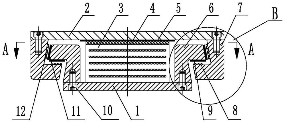
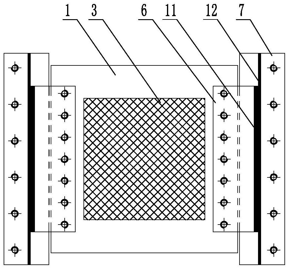
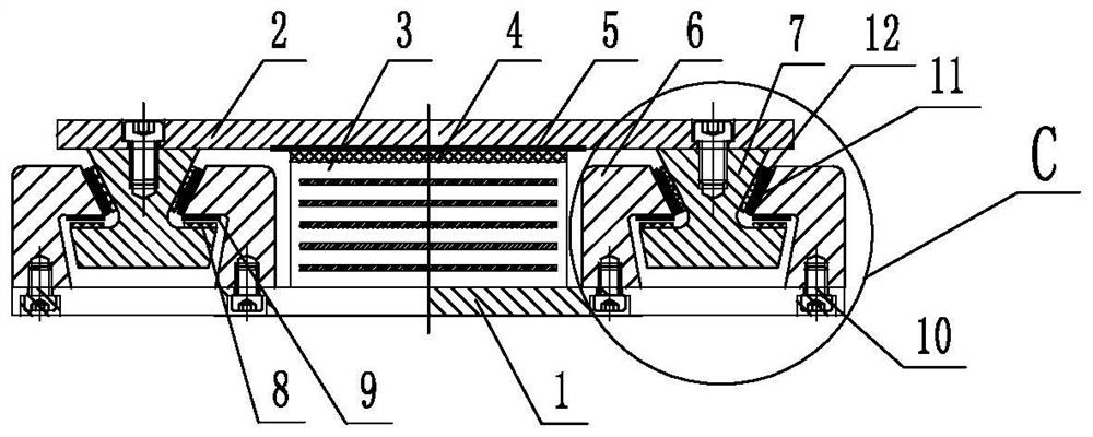
[0048] A tensile sliding rubber bearing, comprising a bearing body 3 and an upper steel plate 2 and a lower steel plate 1 connected up and down the upper steel plate 2 and a lower steel plate 1, and a tensile mechanism and a sliding mechanism are arranged between the upper steel plate 2 and the lower steel plate 1: the The tensile mechanism includes a left tensile mechanism and a right tensile mechanism. The left tensile mechanism and the right tensile mechanism are symmetrically arranged between the upper and lower steel plates on the left and right sides of the support body. The left and right tensile mechanisms have the same structure. It includes an upper tensile steel part and a lower tensile steel part, the upper tensile steel part is connected with the upper steel plate, the lower tensile steel part is connected with the lower steel plate, the lower end of the upper tensile steel part is connected with the upper end of the lower tensile steel part Interlocking to form a ...

Embodiment 2

[0059] A tensile sliding rubber support, the basic structure of which is basically the same as that of Embodiment 1, including a support body 3 and an upper steel plate 2 and a lower steel plate 1 connected up and down the upper steel plate 2 and the lower steel plate 1. Tensile mechanism and sliding mechanism:

[0060] The tensile mechanism includes a left tensile mechanism and a right tensile mechanism symmetrically arranged between the upper steel plate and the lower steel plate on the left and right sides of the support body. The left and right tensile mechanisms have the same structure, including upper tensile steel parts and The lower tensile steel part, the upper tensile steel part is connected with the upper steel plate, the lower tensile steel part is connected with the lower steel plate, and the lower end of the upper tensile steel part is buckled with the upper end of the lower tensile steel part to form a tensile mechanism ;

[0061] The upper tensile steel piece ...


PUM


Abstract

The invention discloses a tensile sliding rubber support. The rubber support is characterized in that a tensile mechanism and a sliding mechanism are arranged between an upper steel plate and a lower steel plate which are connected to the upper part and the lower part of a support body; the tensile mechanism comprises a left tensile mechanism and a right tensile mechanism which are symmetrically arranged between the upper steel plate and the lower steel plate on the left side and the right side of the support body; an upper tensile steel part and a lower tensile steel part which are respectively connected with an upper steel plate and a lower steel plate are further included, a lower end of the upper tensile steel part and an upper end of the lower tensile steel part are mutually buckled to form a tensile mechanism, and an inner angle formed by buckling surfaces is an acute angle; the sliding mechanism comprises a plane sliding pair, a horizontal sliding pair and a limiting sliding pair, the plane sliding pair is arranged between the upper steel plate and the support body, and the horizontal sliding pair and the limiting sliding pair are arranged between the buckling faces of the upper tensile steel piece and the lower tensile steel piece. The support can provide required bearing capacity in a normal state, can provide tensile resistance in the vertical direction in a strong earthquake, and has the functions of limiting on the left side and the right side and sliding in the main displacement direction, so safety of the sliding support and a bridge structure is improved.

Description

technical field [0001] The invention relates to a component for erecting a bridge, in particular to a tension-resistant sliding rubber bearing used in large-span long cantilever bridge structures, such as long-span rigid frame bridges and cable-stayed bridges. Background technique [0002] In the prior art, supports are usually set between the bridge superstructure and the abutment, and the traditional sliding rubber bearings mainly include the following types: ordinary PTFE sliding rubber bearings, LNR horizontal force dispersion sliding rubber bearings and GCBZ plate damping sliding rubber bearing, etc. The above traditional types of sliding rubber bearings only have the function of vertical bearing and have no vertical anti-pullout function. Under the action of earthquakes, it is easy to be pulled out of the air, displaced or even drop the beam. [0003] According to the latest "Code for Seismic Design of Highway Bridges (JTG / T2231-01-2020)", Article 11.5 of the Bridge A...

Claims


Application Information

Patent Timeline
IPC IPC(8): E01D19/04
CPCE01D19/04E01D19/041E01D19/048
Inventor 吕学益莫曲浪韦亮陆资道铭何家荣吴玲正刘志东徐鸿飞梁煜罗明罗秋清黄敦华兰志勋刘伟萍谭晓韦韦华梁
Owner 柳州东方工程橡胶制品有限公司
Learn More