A High Pressure Resistant Dissolvable Bridge Plug
A technology of high pressure resistance and bridge plug, which is applied in the direction of wellbore/well components, sealing/isolation, earthwork drilling and production, etc. The effect of preventing cylinder damage and improving sealing performance
- Summary
- Abstract
- Description
- Claims
- Application Information
AI Technical Summary
Problems solved by technology
Method used
Image

Examples
Embodiment 1
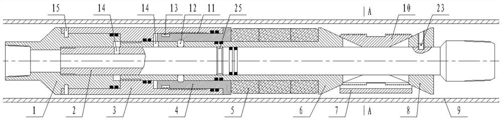
[0034] Such as figure 1 As shown, the present invention includes an upper joint 1 , a central pipe 2 , a rubber cartridge 5 , an upper cone 6 , a lower cone 8 and slips 10 . The above structure is a common structure in the prior art, and will not be repeated here.
[0035] Such as figure 1 As shown, the upper joint 1 is screwed to the upper end of the central tube 2, the upper cone 6 is slidably installed on the central tube 2, the lower cone 8 is fixedly installed on the central tube 2, and the rubber tube 5 is set on the upper cone 6, the upper cone 6 is also equipped with a setting piston 4 and a piston sleeve 3, the side wall of the upper cone 6 is equipped with a lock block 12 that can slide in the radial direction, and the inner wall of the setting piston 4 is connected with the lock block 12 is correspondingly provided with a locking groove, and one end of the slider is inserted into the locking groove, thereby locking the setting piston 4 on the upper cone 6; the out...
Embodiment 2
[0047] The difference between this embodiment and Embodiment 1 is that the locking method of the upper cone 6 has been improved, and the specific improvement methods have the following two points:
[0048] 1. A slip ring 17 is added on the upper cone 6, and a shoulder 18 matching the outer edge of the slip ring 17 is processed on the inner side of the slip 10.
[0049] 2. Between the upper joint 1 and the piston sleeve 3, a C-shaped circlip 13 and a one-way stop thread 11 cooperating with the C-shaped circlip 13 are added.
[0050] In the first embodiment, the setting of the first stage depends on the locking of the locking block 12 after the second stage is started, which requires high machining accuracy of the parts and poor adaptability to well pipes 9 of different diameters.
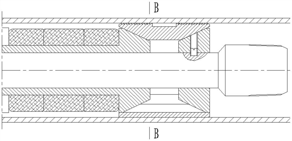
[0051] In this example, in Figure 7 In the state shown, the upper cone 6 can still be further wedged between the central tube 2 and the slip 10, and at the same time, the axial relative position of...
Embodiment 3
[0053] The difference between this embodiment and Embodiment 1 is:
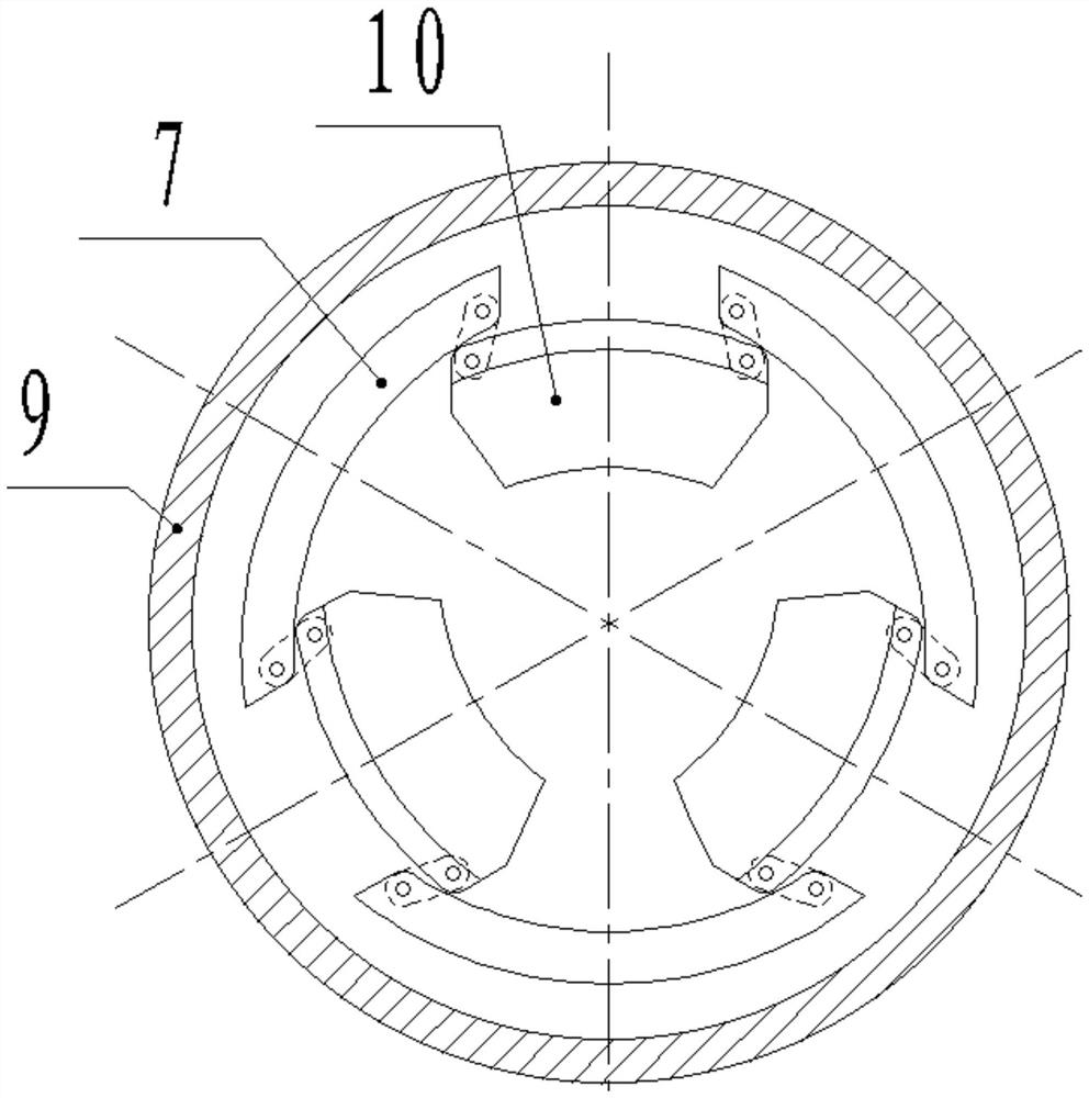
[0054] Such as Figure 8 As shown, a mandrel 20 is installed on the inner side of the central tube 2, and a torsion spring 21 is arranged between the mandrel 20 and the inner wall of the mounting hole where it is located; All are connected with soft rope 19, and central tube 2 side walls are provided with through holes for passing through soft rope 19, and torsion spring 21 is in the state of accumulating energy all the time (that is at least a part of soft rope 19 is always pressed by the elastic force of torsion spring 21 traction); the length of the soft rope 19 between the slips 10 and the mandrel 20 is equal to the maximum distance between the slips 10 and the mandrel 20; the length of the soft rope 19 between the arc plate 7 and the mandrel 20 is longer than that of the arc plate The maximum distance between 7 and the mandrel 20 is large, and the difference is equal to the thickness of the arc plate 7 ...
PUM
 Abstract
Description
Claims
Application Information
 - R&D
- Intellectual Property
- Life Sciences
- Materials
- Tech Scout
- Unparalleled Data Quality
- Higher Quality Content
- 60% Fewer Hallucinations
Browse by: Latest US Patents, China's latest patents, Technical Efficacy Thesaurus, Application Domain, Technology Topic, Popular Technical Reports.
© 2025 PatSnap. All rights reserved.Legal|Privacy policy|Modern Slavery Act Transparency Statement|Sitemap|About US| Contact US: help@patsnap.com