Multi-point testing device and testing method based on autocollimator

An autocollimator and testing device technology, which is applied to measurement devices, optical devices, instruments, etc., can solve the problems of low testing efficiency of MEMS micromirror chips and high cost of packaging and testing, so as to improve production and testing efficiency and reduce packaging and testing. cost, the effect of reducing the overall test time

Inactive Publication Date: 2021-08-06
ANHUI CHINA SCI MW ELECTRONIC TECH CO LTD
View PDF19 Cites 0 Cited by
  • Summary
  • Abstract
  • Description
  • Claims
  • Application Information

AI Technical Summary

Problems solved by technology

[0004] In view of the above-mentioned shortcoming of the prior art, the purpose of the present invention is to provide a kind of multi-point testing device and testing method based on the autocollimator, for solving the problem that the autocollimation measuring instrument exists in the prior art to MEMS micro The testing efficiency of the mirror chip is low, and the cost of packaging and testing is high

Method used


Image

  • Multi-point testing device and testing method based on autocollimator
  • Multi-point testing device and testing method based on autocollimator
  • Multi-point testing device and testing method based on autocollimator

Examples


Embodiment 1

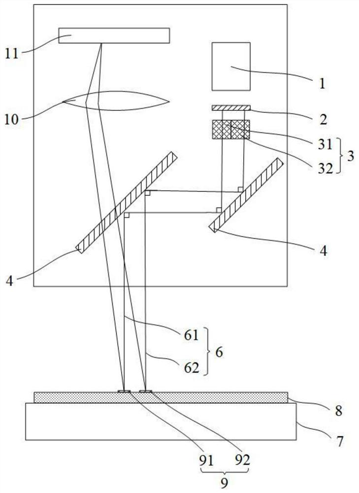
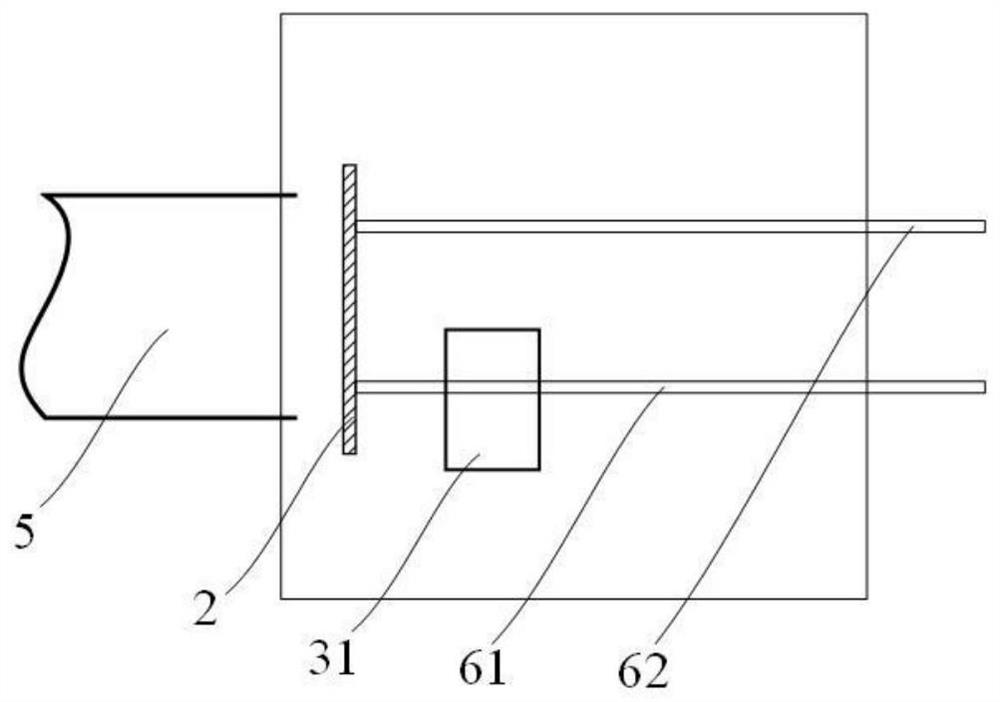
[0069] see figure 1 and figure 2 , the spatial optical switch 3 in the autocollimator-based multi-point testing device provided in this embodiment is composed of only one optical switch (the first optical switch 31). The parallel laser beam 5 produced by the beam expanding and collimating laser light source 1 emits two laser beams through the diaphragm 2, which are respectively the first laser beam 61 and the second laser beam 62, and an optical switch is arranged on the optical path of any one of the laser beams, In this embodiment, one first optical switch 31 is arranged on the optical path of the first laser beam 61 . In addition, the test sequences of the two chips to be tested are different.

[0070] The first optical switch 31 is closed, the first laser beam 61 is blocked by the first optical switch 31, and the second laser beam 62 is not blocked by the optical switch, first test the second laser beam 62 points to the second chip 92 under test. After the test is com...

Embodiment 2

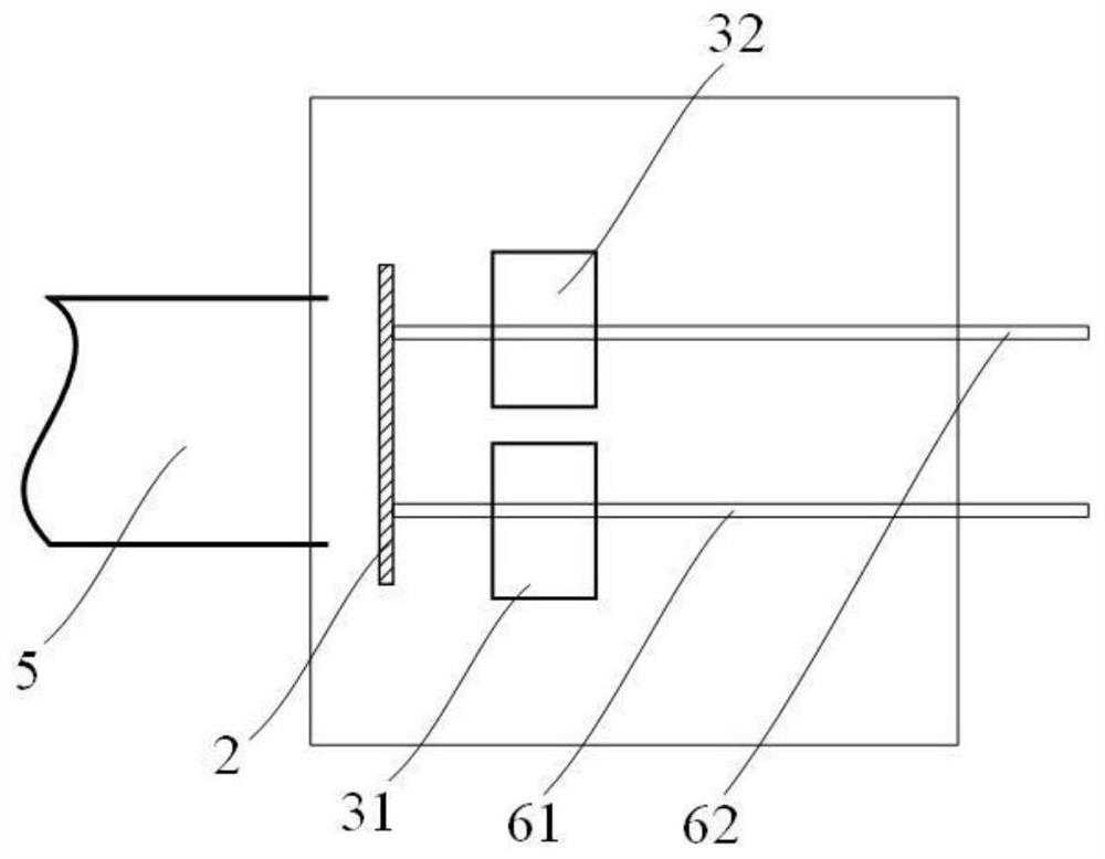
[0072] see figure 1 and image 3 , the spatial optical switch 3 in the autocollimator-based multi-point testing device provided in this embodiment is composed of two optical switches, namely a first optical switch 31 and a second optical switch 32 . The parallel laser beam 5 produced by the beam expanding and collimating laser light source 1 emits two laser beams through the diaphragm 2, which are respectively the first laser beam 61 and the second laser beam 62, and a light beam is respectively arranged on the optical path of the two laser beams. The switches are the first optical switch 31 and the second optical switch 32 respectively. In addition, the test sequences of the two chips to be tested are the same.

[0073] At a certain moment, the first optical switch 31 is turned on, and the second optical switch 32 is turned off to test the first chip under test 91 pointed to by the first laser beam 61; and at the next moment, the first The optical switch 31 is turned off, ...

Embodiment 3

[0075] see figure 1 , Figure 4 and Figure 5 , the spatial optical switch 3 in the autocollimator-based multi-point testing device provided in this embodiment is composed of four optical switches. The parallel laser beam 5 produced by the beam expanding and collimating laser light source 1 emits four beams of laser light through the diaphragm 2, and an optical switch is respectively arranged on the optical path of each laser beam, which are respectively denoted as the first optical switch 31 and the second optical switch. 32. The third optical switch 33 and the fourth optical switch 34. In addition, the test sequences of the four chips to be tested are the same, and the four chips to be tested can be tested sequentially. The difference between this embodiment and the second embodiment is only that the number of laser beams and corresponding lights is increased, and the test method is the same, and will not be repeated here.


PUM


Abstract

The invention provides a multi-point testing device and testing method based on an autocollimator. The multi-point testing device comprises an incident light module which comprises a beam-expanding collimation laser light source, a diaphragm, a spatial light switch and a light path auxiliary lens, wherein the beam-expanding collimation laser light source is used for generating parallel laser beams irradiated on the diaphragm, the diaphragm is used for controlling the width of parallel laser beams, the spatial optical switch is arranged on the light path of emergent light of the diaphragm and is used for controlling the on-off of the laser beams, and the light path auxiliary lens is used for changing the light path of the laser beams so as to irradiate the laser beams on a chip to be detected; and a light receiving module which comprises a light condensing part and an image point receiving screen, wherein the light condensing part is used for irradiating the laser beam reflected by the chip to be detected on the image point receiving screen. According to the multi-point testing device based on the autocollimator, the purposes of greatly improving the production testing efficiency and reducing the sealing testing cost are achieved.

Description

technical field [0001] The invention relates to the field of production and testing of MEMS micromirrors, in particular to a multi-point testing device and testing method based on an autocollimator. Background technique [0002] At present, chip devices based on MEMS are widely used in the field of optical communication. MEMS focuses on ultra-precision machining, and the testing of MEMS devices is different from traditional IC chips, requiring professionally customized testing devices. Based on the requirements of reducing the packaging and testing cost of MEMS chips, improving the single-chip test speed and the number of multi-chip composite tests of special test devices will be the main development direction of MEMS device test devices. [0003] Micromirror products manufactured based on MEMS process technology integrate optical micromirrors and microdrivers, and are the core components of optical MEMS devices. The size of the mirror surface is usually hundreds of microns...

Claims


Application Information

Patent Timeline
Patent Type & Authority Applications(China)
IPC IPC(8): G01B11/26
CPCG01B11/26
Inventor 赵旭东方杰杜铖柯
Owner ANHUI CHINA SCI MW ELECTRONIC TECH CO LTD
Why Eureka
Try Eureka