Supercharge Your Innovation With Domain-Expert AI Agents!

Mueller matrix detection device calibration method

A Mueller matrix and detection device technology, which is applied in the calibration field of Mueller matrix detection devices, can solve the problems of not considering the influence of incident light obliquely entering the Mueller matrix detection device error, and unsatisfactory

Active Publication Date: 2021-08-06
SOUTH CHINA NORMAL UNIVERSITY
View PDF8 Cites 0 Cited by
  • Summary
  • Abstract
  • Description
  • Claims
  • Application Information

AI Technical Summary

Problems solved by technology

[0004] However, the existing calibration methods, such as the Chipman analytical calibration method, do not consider the error caused by the incident light obliquely entering the Mueller matrix detection device during the calibration process, so they cannot meet the requirements for anisotropic samples with a certain incident angle. Make accurate measurements and characterization

Method used


Image

  • Mueller matrix detection device calibration method
  • Mueller matrix detection device calibration method
  • Mueller matrix detection device calibration method

Examples


Embodiment Construction

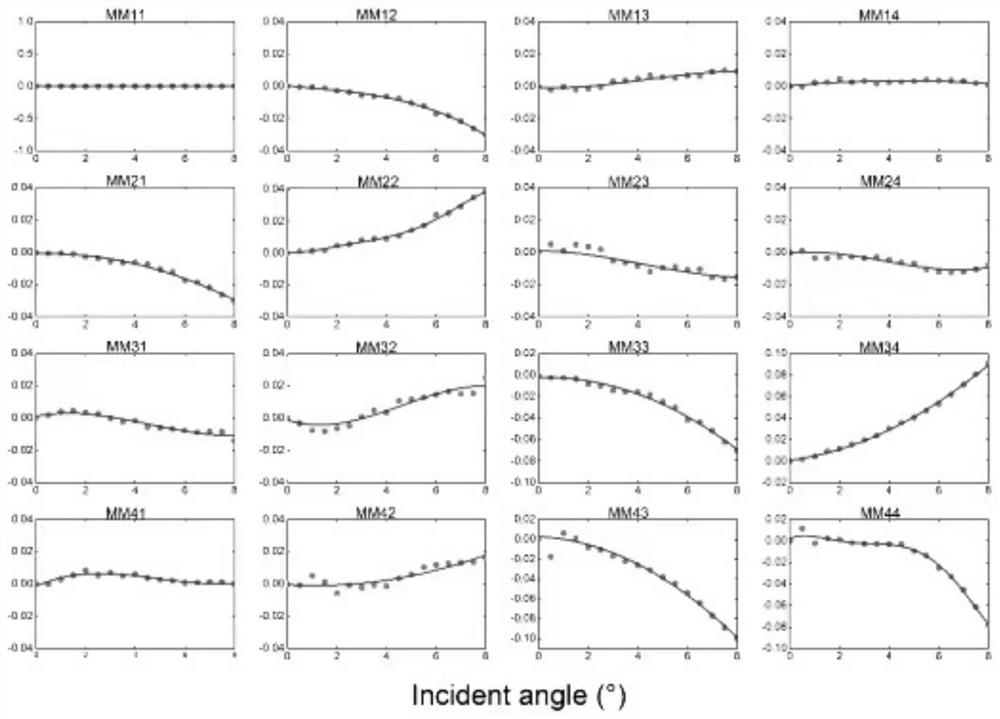
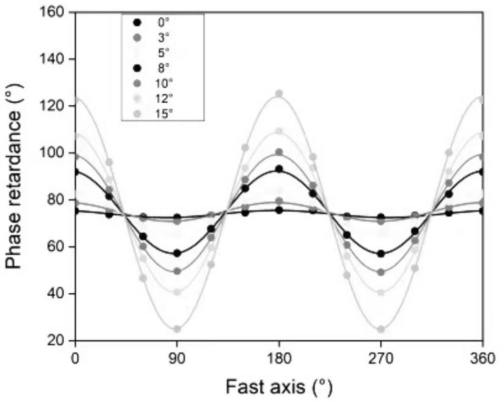
[0046] Based on the fact that the existing Mueller matrix detection device has the wave plate due to improper installation, defects in the processing process or the approximate collimation of the cone beam in the actual optical path, the light is obliquely incident, the applicant uses the existing Mueller matrix detection device The device is transformed into an oblique incidence Mueller matrix detection device, simulating the oblique incidence of incident light to the surface of a quarter-wave plate, and observing the change trend of the Mueller matrix elements of the sample measured under oblique incidence conditions, so as to determine the oblique incidence of light influences.

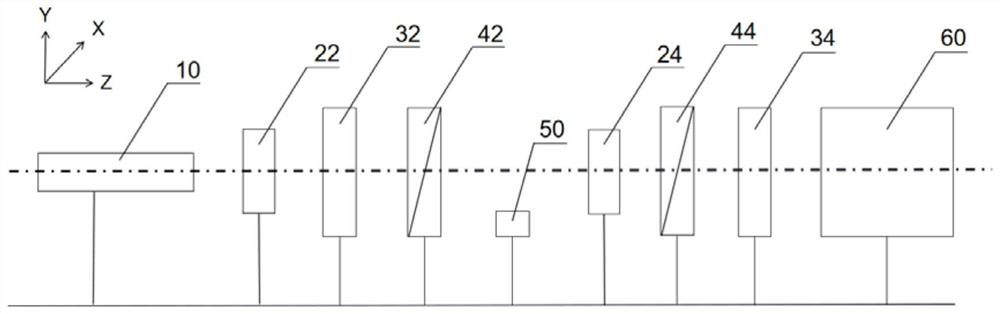
[0047] see figure 1 , figure 1 It is a structural schematic diagram of an oblique incidence Mueller matrix detection device for simulating oblique incidence of light in the present invention. The oblique incidence Mueller matrix detection device comprises a light source 10, a collimator lens 24, ...


PUM


Abstract

The invention discloses a Mueller matrix detection device calibration method, which comprises the following steps: S1, establishing a phase delay perturbation theoretical model when incident light obliquely enters the surfaces of a first wave plate and a second wave plate of a Mueller matrix detection device, so as to establish a relation model of a light intensity value and an error term; S2, measuring a light intensity value I of the standard sample by using the Mueller matrix detection device; S3, substituting the light intensity value I of the standard sample obtained in the step S2 and the known Mueller matrix Msample of the standard sample into an equation set; S4, solving values of all errors x1, x2, x3, x4, x5, x6, x7, x8 and x9 in the relation model of the light intensity values and the error terms through adoption of a numerical calibration method; and S5, calibrating the original instrument matrix F of the Mueller matrix detection device according to the values of all errors solved in the step S4, and reconstructing a calibration instrument matrix F'. The calibration method has the characteristics of simple operation, convenience, reliability, high measurement speed, high precision and the like.

Description

technical field [0001] The invention relates to the technical field of polarization imaging, in particular to a calibration method for a Mueller matrix detection device. Background technique [0002] Polarization imaging is a non-labeling, non-destructive, fast detection technology with sub-wavelength resolution. It is compatible with non-polarization optical imaging technology in hardware. It only needs to add a polarizing module and an analyzing module to realize polarization measurement. Moreover, polarization imaging technology can provide richer sample microstructure information than non-polarization imaging, so it is widely used in various fields such as biomedical diagnosis, material characterization, and military target recognition. In polarization optics, the Mueller matrix is ​​often used to describe the transformation process of the interaction between light and matter. The Mueller matrix can completely characterize all the polarization information of the sample, ...

Claims


Application Information

Patent Timeline
Patent Type & Authority Applications(China)
IPC IPC(8): G01N21/21G06F17/16G06F30/20
CPCG01N21/21G01N21/274G06F17/16G06F30/20
Inventor 唐志列付瑶陈振华
Owner SOUTH CHINA NORMAL UNIVERSITY
Features
  • R&D
  • Intellectual Property
  • Life Sciences
  • Materials
  • Tech Scout
  • Unparalleled Data Quality
  • Higher Quality Content
  • 60% Fewer Hallucinations
Learn More