
Winding AC resistance measurement method and system

A technology of AC resistance and measurement method, applied in the direction of measurement device, measurement of electrical variables, measurement of resistance/reactance/impedance, etc., can solve problems such as increasing the difficulty of project implementation, lack of space, and restricting applications, and expand the measurement frequency range. , the effect of improving the degree of coupling and reducing the difficulty of implementation

Active Publication Date: 2021-08-06
NR ELECTRIC CO LTD +1
View PDF4 Cites 0 Cited by
  • Summary
  • Abstract
  • Description
  • Claims
  • Application Information

AI Technical Summary

Problems solved by technology

At present, the winding loss method based on auxiliary winding mainly has the following disadvantages: (1) Additional auxiliary windings need to be arranged in the magnetic component under test, which increases the difficulty of engineering implementation, and there may not be enough space for arranging auxiliary windings in high power density designs ; (2) The degree of coupling between the auxiliary winding and the measured winding is not high, which limits its application in the field of high power and high frequency

Method used


Image

  • Winding AC resistance measurement method and system
  • Winding AC resistance measurement method and system
  • Winding AC resistance measurement method and system

Examples


Embodiment 1

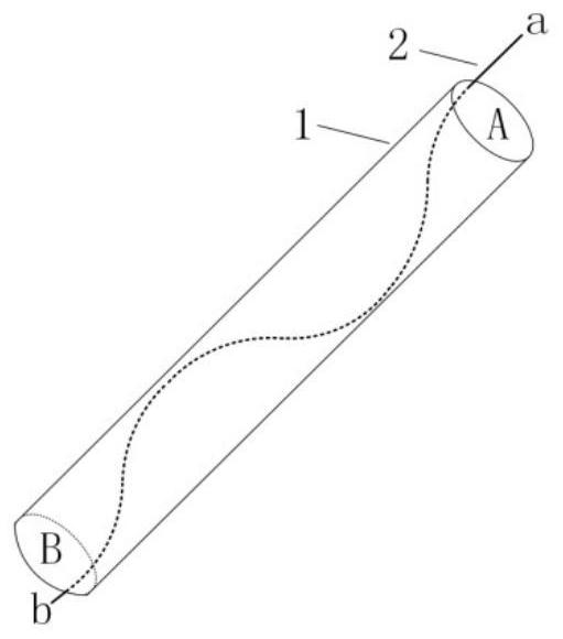
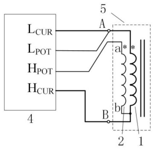
[0051] Example 1, such as figure 1 The schematic diagram of the tested winding and auxiliary winding is shown, the tested winding 1 is a multi-strand enameled stranded wire (Litz wire), the auxiliary winding 2 is a randomly selected single-strand wire in the tested winding 1, and the auxiliary winding 2 and the The other strands in winding 1 are insulated from each other. Since there is no need to additionally arrange auxiliary windings in the magnetic component under test, the difficulty of engineering implementation is reduced. The two ends of the measured winding 1 are respectively B and A, and the two ends of the auxiliary winding 2 are respectively b and a. Terminal a of winding 2 has no direct electrical connection. Due to the tight twisting of the winding 1 under test, the coupling degree between the auxiliary winding 2 and the winding 1 under test is much greater than that when an additional auxiliary winding is arranged, which can be used for high-precision measurem...

Embodiment 2

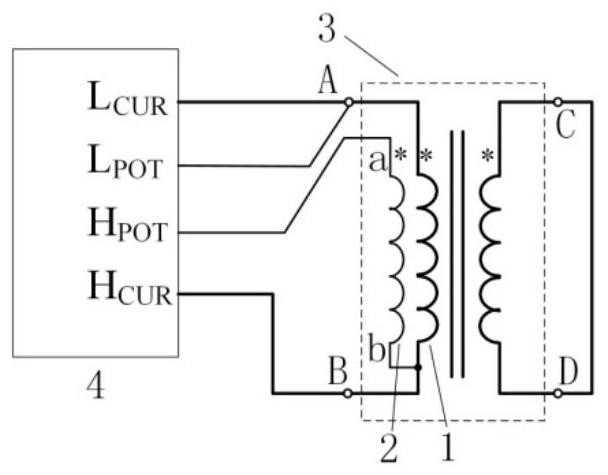
[0053] Example 2, image 3 An embodiment of measuring the AC resistance of a transformer winding by the method of the present invention is shown, and the embodiment includes an impedance measuring instrument 4 and a transformer under test 3 . The other windings in the tested transformer 3 except the tested winding 1 and the auxiliary winding 2 are short-circuited.

[0054]Compared with the prior art, the present invention has the following advantages: (1) It is unnecessary to arrange additional auxiliary windings in the magnetic element under test, which reduces the difficulty of engineering implementation; It is suitable for high-precision measurement of AC resistance of high-power windings, and at the same time expands the measurement frequency range.

[0055] Those skilled in the art should understand that the embodiments of the present application may be provided as methods, systems, or computer program products. Accordingly, the present application may take the form of ...


PUM


Abstract

The invention discloses a winding AC resistance measurement method and system. The method comprises the following steps: randomly selecting a single-strand wire from a measured winding as an auxiliary winding; and measuring the alternating-current resistance value of the measured winding by adopting a four-end pair impedance measurement mode. Compared with the prior art, the method has the advantages that an auxiliary winding does not need to be additionally arranged in the tested magnetic element, so that the engineering implementation difficulty is reduced; the method improves the coupling degree of the auxiliary winding and the measured winding, can be used for the high-precision measurement of the AC resistance of a high-power winding, and enlarges the measurement frequency range at the same time.

Description

technical field [0001] The invention relates to a winding AC resistance measurement method and system, and belongs to the technical field of magnetic components such as transformers and inductors and their parameter measurement. Background technique [0002] Improving the operating frequency of magnetic components such as transformers and inductors is the main means to greatly reduce their volume and quality, which provides the possibility to increase system power density and reduce system cost. In the design of high-power high-frequency magnetic components, the use of Litz wire winding is an effective method to reduce the loss of high-frequency windings. The complex structure of Litz wire winding makes it very difficult to calculate the AC resistance of the winding, so it is of great significance to study a reliable measurement method of winding loss. [0003] In order to reduce the influence of the induced voltage in the magnetic element on the measurement accuracy of the...

Claims


Application Information

Patent Timeline
IPC IPC(8): G01R27/02
CPCG01R27/02
Inventor 骆仁松汪涛张茂强虞晓阳
Owner NR ELECTRIC CO LTD
Learn More