Adjustable manual lifting table

An adjustable technology for lifting tables, applied in the field of lifting tables, can solve the problems of slow adjustment speed, easy to rust, and danger, and achieve the effect of saving time and effort in the operation process

Pending Publication Date: 2021-08-10
SHANGHAI TENGFEI COMM EQUIP IND CO LTD
View PDF0 Cites 1 Cited by
  • Summary
  • Abstract
  • Description
  • Claims
  • Application Information

AI Technical Summary

Problems solved by technology

[0003] At present, there are many ways to realize the lifting of the manual lifting table. The more common way is to use the handle to shake, and the relative rotation of the screw structure through the transmission device will cause relative displacement, thereby changing the height of the desktop and adjusting it. It is labor-saving but the adjustment speed is slow. And the mechanism needs to be maintained more frequently, otherwise it is easy to rust or get stuck, and it takes more physical strength to lift the desktop; and the angle of the corresponding structure can be changed through the latch and the rotating mechanism, thereby changing the height of the desktop, but it is more inconvenient. The tightness will have certain dangers, the adjustment speed is slow, and generally only discrete gears can be set; there are also those who directly use the preset jacks and pins to change the height of the tabletop. Although the structure is simple, there are only a limited number of discrete gears. The location is available, and the operation is dangerous, and there are certain requirements for the user's physical strength

Method used


Image

  • Adjustable manual lifting table
  • Adjustable manual lifting table
  • Adjustable manual lifting table

Examples


Embodiment Construction

[0046] The present invention will be further described below according to the accompanying drawings.

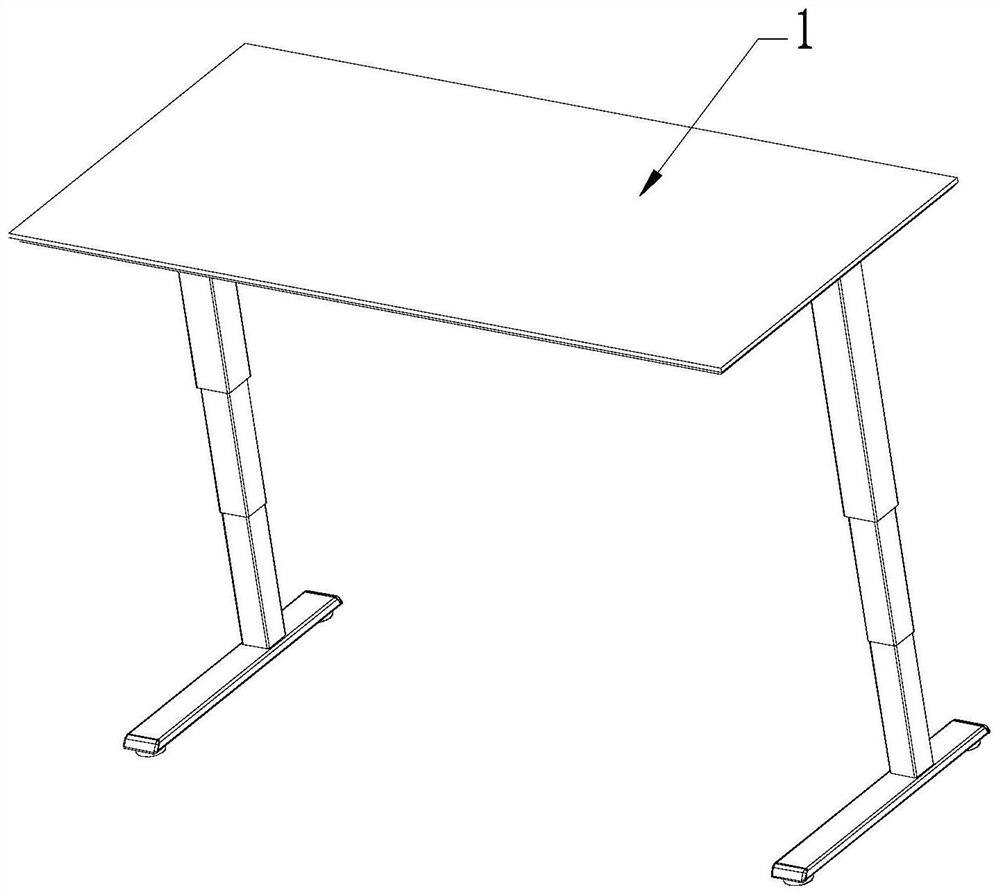
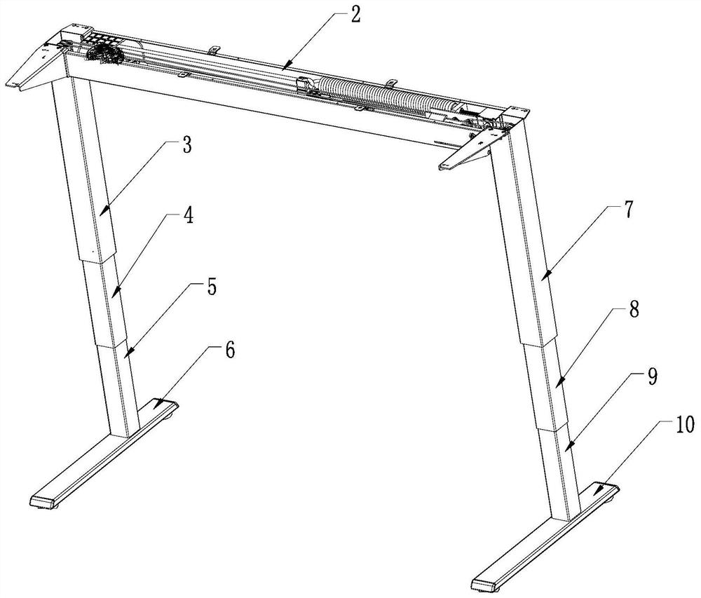
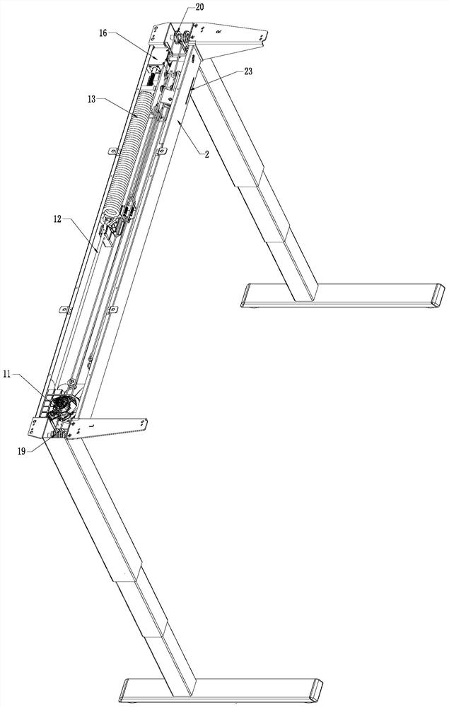
[0047] Such as Figure 1 to Figure 24As shown, the upper end of the crossbeam 2 is connected to the work surface 1, and the left and right sides of the lower end of the crossbeam 2 are respectively connected to the left lifting table leg assembly and the right lifting table leg assembly; Connect one end of the cam disc drive rope 12, the other end of the cam disc drive cord 12 is connected to the cam disc assembly 11; the other end of the driving spring 13 is connected to the spring tension regulator 16; 21 and one end of the auxiliary steel rope 22, the other end of the active steel rope 21 is divided into two routes, respectively connected to one end of the left active rope 17 and the right active rope 18, and the other end of the auxiliary steel rope 22 is divided into two routes, respectively connected to the left auxiliary rope 14 and the right auxiliary rope 15; the le...


PUM


Abstract

The invention relates to the technical field of lifting tables, in particular to an adjustable manual lifting table. The adjustable manual lifting table is characterized in that the upper end of a cross beam is connected with a working table top, and the left side and the right side of the lower end of the cross beam are connected with a left lifting table leg assembly and a right lifting table leg assembly respectively; a driving spring is arranged on one side in the cross beam, one end of the driving spring is connected with one end of a cam disc driving rope, and the other end of the cam disc driving rope is connected with a cam disc assembly; the other end of the driving spring is connected with a spring tension regulator; and one end of a driving steel wire rope and one end of an auxiliary steel wire rope are wound on the cam disc assembly in opposite directions, the other end of the driving steel wire rope is divided into two paths which are respectively connected with one ends of a left driving rope and a right driving rope, and the other end of the auxiliary steel wire rope is divided into two paths which are respectively connected with a left auxiliary rope and a right auxiliary rope. Compared with the prior art, the height of the table top can be continuously adjusted, time and labor are saved in the operation process, and the table is widely used in offices, families and the like.

Description

technical field [0001] The invention relates to the technical field of lift tables, in particular to an adjustable manual lift table. Background technique [0002] The usual way of working is fixed-height desks, where employees sit and sit in a relatively fixed posture. Over time, it will cause symptoms such as back pain, shoulder and neck discomfort, and serious health problems. Currently, the height-adjustable height-adjustable desks on the market are generally electric desks, because of their power requirements, the application occasions are relatively limited. [0003] At present, there are many ways to realize the lifting of the manual lifting table. The more common way is to use the handle to shake, and the relative rotation of the screw structure through the transmission device will cause relative displacement, thereby changing the height of the desktop and adjusting it. It is labor-saving but the adjustment speed is slow. And the mechanism needs to be maintained mor...

Claims


Application Information

Patent Timeline
Patent Type & Authority Applications(China)
IPC IPC(8): A47B9/00A47B9/12A47B9/20A47B13/02
CPCA47B9/00A47B9/12A47B9/20A47B13/02A47B2200/0054
Inventor 潘文明汤永飞
Owner SHANGHAI TENGFEI COMM EQUIP IND CO LTD
Why Eureka
Try Eureka