Test tube storage box for hematology department

A technology for storage boxes and test tubes, applied in the direction of test tube holders/clamps, etc., can solve problems such as poor sealing, single test tube storage box, and difficult operation, and achieve good sealing, improved work efficiency, and strong shock absorption effect

Active Publication Date: 2021-08-10
浙江元勤生物医药科技有限公司
View PDF7 Cites 4 Cited by
  • Summary
  • Abstract
  • Description
  • Claims
  • Application Information

AI Technical Summary

Problems solved by technology

[0005] In order to overcome the shortcomings of the traditional test tube storage box, which is relatively simple and difficult to operate, when placing the test tube, the test tube should be in contact with the test tube rack in the storage box, and if it is accidentally shaken, the test tube will be broken and the airtightness is poor. The technical problem to be solved: provide A hematology test tube storage box with good clamping effect, shock absorption function, and prevention of test tube damage

Method used


Image

  • Test tube storage box for hematology department
  • Test tube storage box for hematology department
  • Test tube storage box for hematology department

Examples


Embodiment 1

[0030] A kind of hematology test tube storage box, such as figure 1 , figure 2 , image 3 , Figure 4 and Figure 5 As shown, a storage box 1, a lifting mechanism 2 and a placement mechanism 3 are included. The inside of the storage box 1 is symmetrically provided with a lifting mechanism 2, and the lifting mechanism 2 is equipped with a placement mechanism 3.

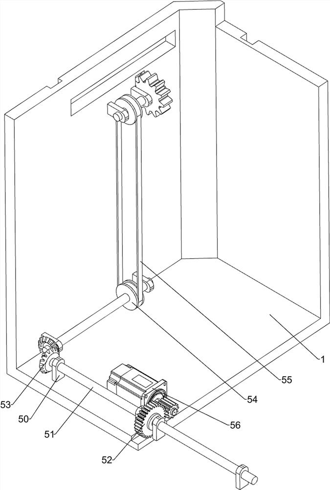
[0031] The lifting mechanism 2 includes a first support block 20, a first gear 21, a lifting frame 22, a rack 23 and a first limit block 24, and the upper side of the storage box 1 is symmetrically provided with the first support block 20 on the left and right sides. The inner side of the first support block 20 is provided with a first gear 21 which is rotatable, and the left and right sides of the inside of the storage box 1 are slidingly provided with a lifting frame 22. The first gear 21 is meshed, and the upper side of the storage box 1 is provided with a first limiting block 24 , and the first limiting block ...

Embodiment 2

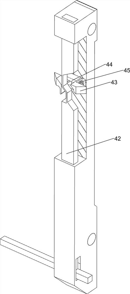
[0035] On the basis of Example 1, such as Figure 6 , Figure 7 , Figure 8 , Figure 9 , Figure 10 and Figure 11 As shown, an unlocking assembly 4 is also included, and the unlocking assembly 4 includes a slide bar 40, a first wedge block 41, a connecting rod 42, a second wedge block 43, a first guide rod 44 and a first spring 45, inside the lifting frame 22 Two slide bars 40 are arranged symmetrically up and down on both sides of the left and right sides. Elastic parts are connected between the slide bars 40 and the lifting frame 22. The slide bars 40 are all matched with the first stopper 24. The upper and lower symmetrical sliding type is provided with the first wedge-shaped block 41, and the first wedge-shaped block 41 cooperates with the slide bar 40 in a sliding manner. Three pairs of first guide rods 44 are symmetrically arranged up and down on the left and right sides of the elevator frame 22, and each pair of first guide rods The number of 44 is two, and the l...


PUM


Abstract

The invention relates to a test tube storage box, and especially relates to a test tube storage box for the hematology department. According to the test tube storage box for the hematology department, the clamping effect is good, the damping function is achieved, and test tubes are prevented from being damaged. According to the technical scheme, the test tube storage box for the hematology department comprises: a storage box body, wherein lifting mechanisms are symmetrically arranged on the inner side of the storage box body; and a storage mechanism arranged on the lifting mechanisms. Under the action of the output shaft of a motor, a full gear, a second gear, a second rotating rod and a bevel gear on the motor are driven to rotate, then a transmission wheel, a belt and a first gear are driven to rotate, the first gear rotates to drive a rack and a lifting frame to move upwards, the lifting frame does not need to be manually moved upwards, and the working efficiency of people is effectively improved.

Description

technical field [0001] The invention relates to a test tube storage box, in particular to a test tube storage box for blood department. Background technique [0002] There are many types of test tubes, which are one of the most commonly used equipment in the medical field. They are usually used to store body fluids and blood. After the blood is collected, it will be stored in the test tube, and then the test tube will be moved to the laboratory for testing. [0003] In the field of medical testing, the blood of the test object is usually stored in test tubes, and then these samples are tested. Before collecting blood, the test tube needs to be taken out of the storage box. At present, the traditional test tube storage box is relatively simple and difficult to operate. , When placing the test tube, make the test tube contact with the test tube rack in the storage box. If people shake it carelessly, the test tube will break, the sealing is poor, and the work efficiency of the ...

Claims


Application Information

Patent Timeline
Patent Type & Authority Applications(China)
IPC IPC(8): B01L9/06
CPCB01L9/06Y02E30/30
Inventor 钟延丰
Owner 浙江元勤生物医药科技有限公司
Why Eureka
Try Eureka