A device and method for rotating molten steel in a tundish

A technology of rotating device and tundish, which is applied in metal processing equipment, manufacturing tools, casting melt containers, etc., can solve the problems of large structural transformation, complicated operation and power consumption of the tundish, and achieves the promotion of collision growth and strengthening. Rotation, simple structure effect

Active Publication Date: 2022-04-08
NORTHEASTERN UNIV LIAONING +1
View PDF11 Cites 0 Cited by
  • Summary
  • Abstract
  • Description
  • Claims
  • Application Information

AI Technical Summary

Problems solved by technology

The swirl tundish installs a swirl chamber in the injection area of ​​the long nozzle of the ladle. The molten steel flows into the swirl chamber from the bottom of the swirl chamber along the tangential direction. The rotation of the inclusions promotes the collision aggregation of the inclusions; the centrifugal tundish uses a magnetic field to rotate the molten steel to promote the floating and separation of non-metallic inclusions in the molten steel, but this method is more complicated to operate, consumes electric energy, and has a higher cost
The rotating flow of molten steel in the tundish also has a positive effect on the removal of inclusions, such as a centrifugal tundish that uses a magnetic field to rotate the molten steel. The tundish is composed of a swirl chamber and a rectangular chamber. The steel entering the swirl chamber The liquid rotates under the action of a magnetic field to promote the collision polymerization of inclusions. Although this method has a positive effect on improving the removal rate of inclusions, its operation is more complicated, requiring a large structural modification of the original tundish and consuming electric energy. ,higher cost

Method used


Image

  • A device and method for rotating molten steel in a tundish
  • A device and method for rotating molten steel in a tundish
  • A device and method for rotating molten steel in a tundish

Examples


Embodiment 1

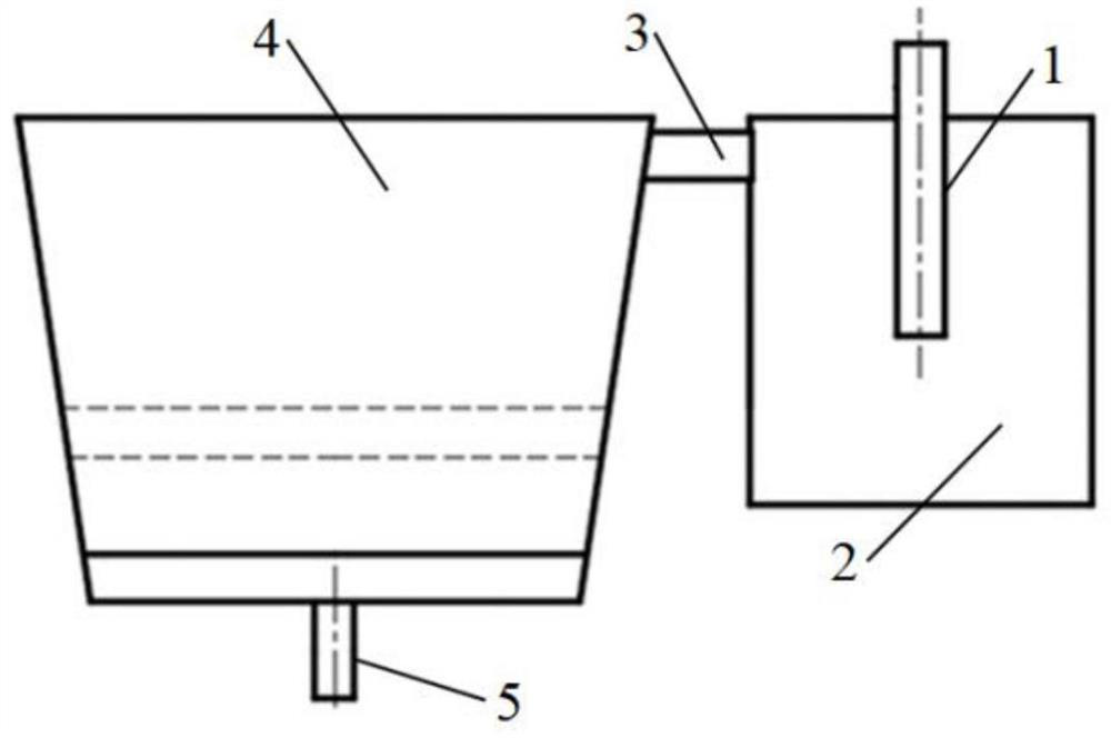
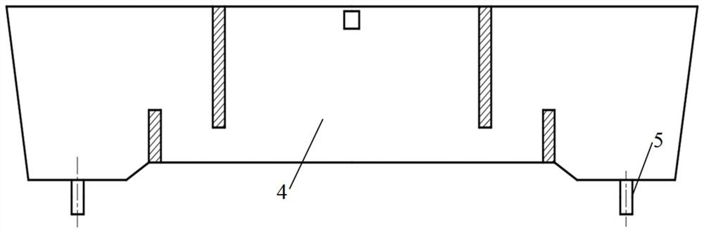
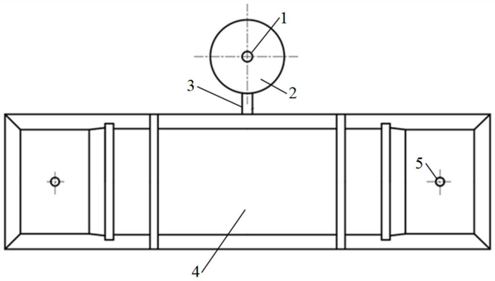
[0045] Such as Figure 7-8 As shown, the height of the molten steel surface 8 of the external tundish swirl chamber 2 in the molten steel rotating device of this embodiment is 800 mm, and the inner diameter of the external tundish swirl chamber 2 is 700 mm; the swirl flow below the ladle shroud 1 The generating device 9 is a cube with a height of 200mm. There are 2 swirl outlets 10, which are linear with a horizontal angle θ of 45°; week. The average diameter of inclusions is increased from 3.90 μm to 4.13 μm by using the molten steel rotating device provided in this embodiment.

Embodiment 2

[0047] Such as Figure 9-11 As shown, the height of the molten steel surface 8 of the external tundish swirl chamber 2 in the molten steel rotating device of this embodiment is 800 mm, and the inner diameter of the external tundish swirl chamber 2 is 700 mm; the swirl flow below the ladle shroud 1 The generating device 9 is a cube with a height of 200 mm. There are 4 swirl outlets 10, which are linear with a horizontal angle θ of 60°; week. The average diameter of the inclusions is increased from 3.90 μm to 4.19 μm by using the molten steel rotating device provided in this embodiment.

Embodiment 3

[0049] Such as Figure 12 As shown, the height of the molten steel surface 8 of the external tundish swirl chamber 2 in the molten steel rotating device of this embodiment is 800 mm, and the inner diameter of the external tundish swirl chamber 2 is 700 mm; the swirl flow below the ladle shroud 1 The generating device 9 is a cylinder with a height of 150mm, and there are 6 swirl outlets 10, which are arc-shaped; the swirl guide rails 6 have a rotation height of 500mm, and the number is 4, each of which rotates 2 times. The average diameter of the inclusions is increased from 3.90 μm to 4.23 μm by using the molten steel rotating device provided in this embodiment.

[0050] The rotating molten steel promotes the centripetal movement of inclusions while uniform composition and temperature, which is beneficial to the collision aggregation of inclusions, and improves the removal efficiency of inclusions and the cleanliness of molten steel. The method for swirling molten steel descr...


PUM

PropertyMeasurementUnit
heightaaaaaaaaaa
heightaaaaaaaaaa
widthaaaaaaaaaa

Abstract

The invention relates to a device and method for rotating molten steel in a tundish, comprising a tundish body and an external tundish swirl chamber, the external tundish swirl chamber communicates with the tundish body through a molten steel flow pipe; The center of the external tundish swirl chamber; a swirl generating device is arranged between the outlet end of the ladle shroud and the inner bottom surface of the external tundish swirl chamber, and the upper and lower ends of the swirl generating device are respectively connected to the ladle shroud and the outer The inner bottom surface of the swirl chamber of the tundish is fixed in contact; the swirl generating device is provided with several swirl outlets, and the molten steel flows into the swirl chamber of the external tundish from the swirl outlets; the external tundish A plurality of spiral swirl guide rails are arranged on the side wall of the swirl chamber, and diversion grooves are formed between the plurality of spiral swirl flow guide rails, and the swirl direction of the flow diversion grooves is set along the direction of the swirl outlet. The invention can promote the centripetal movement of the inclusions, increase the collision probability of the inclusions, and provide conditions for the growth of the inclusions.

Description

technical field [0001] The invention belongs to the technical field of continuous casting, and in particular relates to a rotating device and method for molten steel in a tundish. Background technique [0002] In modern steel production, the contribution of continuous casting technology is increasing. The application of continuous casting technology not only improves the mechanization and automation level of production, but also saves energy and improves the yield and quality of products. The molten steel in the ladle flows into the turbulent flow controller in the tundish through the long nozzle of the ladle, and the molten steel flows out from the turbulent flow controller and changes the movement path under the flow control of the retaining wall and dam, prolonging the residence time of the molten steel and promoting The further floating removal of inclusions in the molten steel improves the cleanliness of the molten steel. The existence of inclusions in the tundish will...

Claims


Application Information

Patent Timeline
Patent Type & Authority Patents(China)
IPC IPC(8): B22D41/50B22D41/00
CPCB22D41/507B22D41/00
Inventor 刘志远罗志国闫宝新顾英杰
Owner NORTHEASTERN UNIV LIAONING
Why Eureka
Try Eureka