Oil painting brush cleaning device

A technology for cleaning devices and oil paint brushes, which can be used in decorative art and painting tools to solve the problems of brush hair falling off and uneven painting layers, and achieve the effect of preventing uneven layers

Pending Publication Date: 2021-08-10
NINGBO DAHONGYING UNIV
View PDF3 Cites 0 Cited by
  • Summary
  • Abstract
  • Description
  • Claims
  • Application Information

AI Technical Summary

Problems solved by technology

[0003] In summary, the present inventors have found that the existing cleaning device mainly has the following defects: during the corresponding cleaning process of the cleaning device, the brush hairs will fall off a little under the corresponding cleaning effect, resulting in The brush hairs will be mixed with the cleaning solution to float on the surface of the cleaning solution, so that the brush hairs will be directly formed after the cleaning solution is used to clean the oil paintbrush again. The brush hairs are crossed and combined together, resulting in uneven painting levels in the subsequent use of the brush

Method used


Image

  • Oil painting brush cleaning device
  • Oil painting brush cleaning device
  • Oil painting brush cleaning device

Examples


Embodiment 1

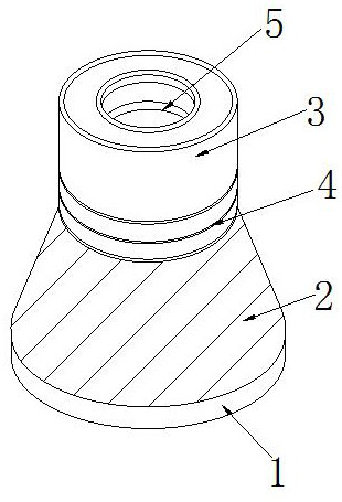
[0028] Figure 1 to Figure 6 Shown:

[0029] The invention provides an oil paint brush cleaning device,

[0030] Its structure includes a positioning seat 1, a cleaning cylinder 2, a positioning channel 3, a connecting shaft 4, and an insertion end 5. 4 is embedded in the lower end of the positioning channel 3, and the insertion end 5 is integrated with the positioning channel 3.

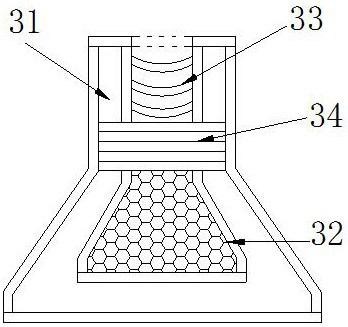
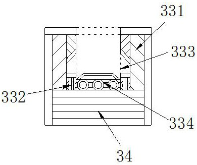
[0031] The positioning passage 3 is provided with an installation groove 31, a partition dish 32, an insertion passage 33, and a balance weight 34. The installation groove 31 communicates with the partition dish 32, and the insertion passage 33 is installed on the upper end of the partition dish 32. The balance The block 34 is embedded in the lower end of the insertion channel 33. The balance block 34 is in a solid state and forms a cuboid shape. The balance block 34 can be effectively fixed on the upper end of the partition dish 32 through its solid state and cuboid shape and is stable. Insert c...

Embodiment 2

[0039] Figure 7 to Figure 9 Shown:

[0040] The invention provides an oil paint brush cleaning device,

[0041] Its structure comprises that described partition dish 32 is provided with hole 321, chassis 322, partition net 323, disassembly block 324, and described hole 321 communicates with chassis 322, and described partition net 323 is installed on the upper end of chassis 322, and described disassembly block 324 Embedded on both sides of the partition net 323, the disassembly block 324 is provided with one piece on both sides of the lower end of the partition net 323. The disassembly block 324 can effectively play a role in the subsequent disassembly and maintenance of the partition net 323 through its own quantity. Shortcut effect.

[0042] Wherein, the chassis 322 is provided with an outer frame c1, a groove c2, a concentration block c3, and a guide block c4. The outer frame c1 and the groove c2 are integrated, and the concentration block c3 is embedded in the groove c...


PUM


Abstract

The invention provides an oil painting brush cleaning device. The oil painting brush cleaning device structurally comprises a positioning seat, a cleaning cylinder, a positioning channel, a connecting shaft and an inserting end, wherein the positioning seat is fixedly connected with the cleaning cylinder, the positioning channel is communicated with the cleaning cylinder, the connecting shaft is embedded into the lower end of the positioning channel, and the inserting end and the positioning channel are integrated. According to the oil painting brush cleaning device, under the mutual cooperation of a partition vessel installed in a positioning channel and a moving device, after an oil painting brush is inserted, driving wheels can be effectively driven through contact wheels, and a rotating ring continuously rotates, so that the oil painting brush can rotate along with rotation of the rotating ring, and the cleaning efficiency of the oil painting brush is improved; and after cleaning is completed, the oil painting brush is pulled out through squeezers, water in the oil painting brush can be continuously squeezed out, and meanwhile, fallen hair is pushed out to make the oil painting brush restore the original shape, so that the phenomenon of uneven layers generated when the oil painting brush is used subsequently can be effectively prevented.

Description

technical field [0001] The invention relates to the field of oil paint brush cleaning, more specifically to an oil paint brush cleaning device. Background technique [0002] The bristles of oil paint brushes are usually composed of pig bristles and a small amount of wolf hair and chemical fiber materials, so that after the painting is completed, the brush bristles can be thoroughly cleaned by a special cleaning device, thereby achieving the effect of replacing hands for washing, making it possible to Improve cleaning efficiency; [0003] In summary, the present inventors have found that the existing cleaning device mainly has the following defects: during the corresponding cleaning process of the cleaning device, the brush hairs will fall off a little under the corresponding cleaning effect, resulting in The brush hairs will be mixed with the cleaning liquid to float on the surface of the cleaning liquid, so that the brush hairs and the cleaning liquid will directly form a ...

Claims


Application Information

Patent Timeline
Patent Type & Authority Applications(China)
IPC IPC(8): B44D3/00
CPCB44D3/00
Inventor 王鹏
Owner NINGBO DAHONGYING UNIV
Why Eureka
Try Eureka