
Machining platform for high-rise steel structure machining and machining method of machining platform

A technology for processing platforms and steel structures, applied in the direction of manufacturing tools, lifting devices, electrical components, etc., can solve problems such as inconvenience, and achieve the effect of preventing uneven bending, reducing installation steps and use costs

Inactive Publication Date: 2021-07-13
武汉市达人联盟房地产投资发展有限公司
View PDF1 Cites 0 Cited by
  • Summary
  • Abstract
  • Description
  • Claims
  • Application Information

AI Technical Summary

Problems solved by technology

The steel structure processing platform in the above-mentioned patents has the following disadvantages: four traveling wheels are used to roll and connect with the top of the first track to limit the position of the processing platform. However, during installation, the track needs to be laid to complete the movement of the processing platform. very inconvenient

Method used


Image

  • Machining platform for high-rise steel structure machining and machining method of machining platform
  • Machining platform for high-rise steel structure machining and machining method of machining platform
  • Machining platform for high-rise steel structure machining and machining method of machining platform

Examples


Embodiment 1

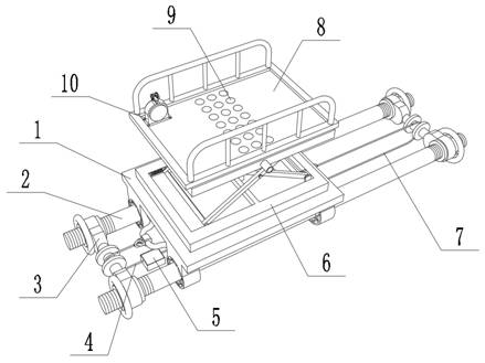
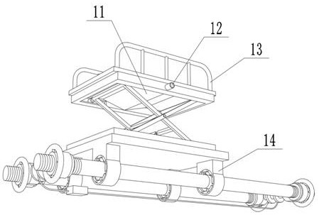
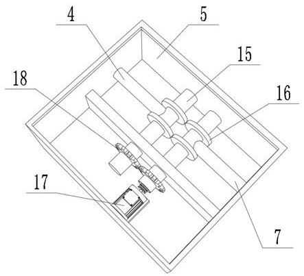
[0042] A processing platform for high-rise steel structure processing, such as figure 1 , 2 , 4 and 5, including a mobile platform 1 and two steel pipes 2; the four corners of the outer wall of the bottom of the mobile platform 1 are respectively welded with a sliding frame 14, and the inner wall on one side of the sliding frame 14 is provided with a sliding opening 28, and the sliding opening 28 is internally provided with Rolling mechanism, each steel pipe 2 is slidably connected to the inside of the two sliding ports 28 through the rolling mechanism, and the two ends of the two steel pipes 2 are respectively welded with threaded rods 19, and the outer walls of the two adjacent threaded rods 19 pass through the mounting holes provided on them respectively. The component is fixed with a limit rod 21, and the outer wall of the limit rod 21 is clamped with two limit plates 22, and the outer walls of two adjacent sliding frames 14 are fixed with the same connecting frame 27, and...

Embodiment 2

[0048] A processing platform for high-rise steel structure processing, such as figure 1 and 2 As shown, in order to be able to adjust the height; the present embodiment makes the following improvements on the basis of Embodiment 1: the outer wall of the top of the mobile platform 1 is provided with a lifting platform 6, the outer wall of the top of the lifting platform 6 is provided with a working platform 8, and the top of the working platform 8 There are more than two collection ports 9 on the outer wall, a funnel 11 is fixed on the outer wall at the bottom of the working platform 8, the funnel 11 is connected to the collecting port 9, a sewage pipe 12 is clipped on the outer wall of one side of the funnel 11, and the two sides of the outer wall on the top of the working platform 8 are respectively provided Guardrail 13 is arranged, and the outer wall of working platform 8 top is fixed with fixed frame 10 by bolt, and fixed frame 10 interior is provided with adjusting mechan...

Embodiment 3

[0052] A processing method for a processing platform for high-rise steel structure processing, comprising the following steps:

[0053] S1: Pass the two steel pipes 2 through the four corresponding sliding frames 14 in turn, the rotating ball 25 rolls on the inner wall of one side of the groove, the rotating ball 25 is matched with the round cover 30, and under the action of the adjusting spring 29, Push the rotating ball 25 into contact with the steel pipe 2 to prevent the steel pipe 2 from being bent and uneven, which may cause the phenomenon of movement jamming;

[0054] S2: Weld the threaded rod 19 at both ends of the steel pipe 2, then hold the runner 20, and screw the rotating sleeve 23 on the threaded rod 19, thereby completing the connection of the two steel pipes 2;

[0055] S3: Then use rope one 4 and rope two 7 to connect two hanging rings 26, rope one 4 and rope two 7 are respectively located between the two corresponding limit plates 22, rope one 4 and rope two 7 ...


PUM


Abstract

The invention discloses a machining platform for high-rise steel structure machining and a machining method of the machining platform, relates to the technical field of high-rise steel structures, and aims at solving the problem that rails need to be laid. The equipment comprises a moving platform and two steel pipes, wherein sliding frames are arranged at the four corners of the outer wall of the bottom of the moving platform respectively, sliding openings are formed in the inner walls of one sides of the sliding frames, rolling mechanisms are arranged in the sliding openings, and each steel pipe is slidably connected into two sliding openings through the corresponding rolling mechanisms. The machining method of the equipment comprises the following steps that the steel pipes penetrate through the sliding frames; rotating sleeves are screwed on threaded rods; and two hanging rings are connected through a first rope and a second rope. According to the equipment, the moving platform and the two steel pipes are arranged, the two steel pipes sequentially penetrate into the four corresponding sliding frames respectively, the first rope and the second rope are wound and unwound through a winding mechanism to control the moving platform to slide on the steel pipes, the two steel pipes are used for limiting the moving platform, and installation is convenient.

Description

technical field [0001] The invention relates to the technical field of high-rise steel structures, in particular to a processing platform for processing high-rise steel structures and a processing method thereof. Background technique [0002] In the prior art, the steel structure is a structure composed of steel materials, which is one of the main building structure types. The structure is mainly composed of steel beams, steel columns, steel trusses and other components made of section steel and steel plates. Each component or The components are usually connected by welds, bolts or rivets; general steel structure processing parts are carried out on the steel structure processing platform. [0003] After searching, the Chinese patent application number is 201811282531.9, which discloses a steel structure processing platform, which includes two first rails arranged in parallel, and two first rails are welded with two parallel to the first rails. Two rails, two first rails and...

Claims


Application Information

Patent Timeline
IPC IPC(8): B25H5/00B66F11/04H02G3/02
CPCB25H5/00B66F11/042H02G3/02
Inventor 胡俊元刘伟
Owner 武汉市达人联盟房地产投资发展有限公司
Learn More