
Hole lamp processing technology

A processing technology and hole lamp technology, used in lighting and heating equipment, lighting devices, light sources, etc., can solve the problems of uneven surface of lamp sockets, affecting the lighting effect of LED lights, etc., to prevent unevenness and prevent drill chips from falling. , the effect of narrowing the gap

Inactive Publication Date: 2018-09-21
道真自治县梦幻灯饰有限公司
View PDF6 Cites 0 Cited by
  • Summary
  • Abstract
  • Description
  • Claims
  • Application Information

AI Technical Summary

Problems solved by technology

[0003] The purpose of the present invention is to provide a hole lamp processing technology to solve the problem that the uneven surface of the lamp holder affects the lighting effect of the LED lamp during the processing process

Method used


Image

  • Hole lamp processing technology
  • Hole lamp processing technology

Examples


Embodiment

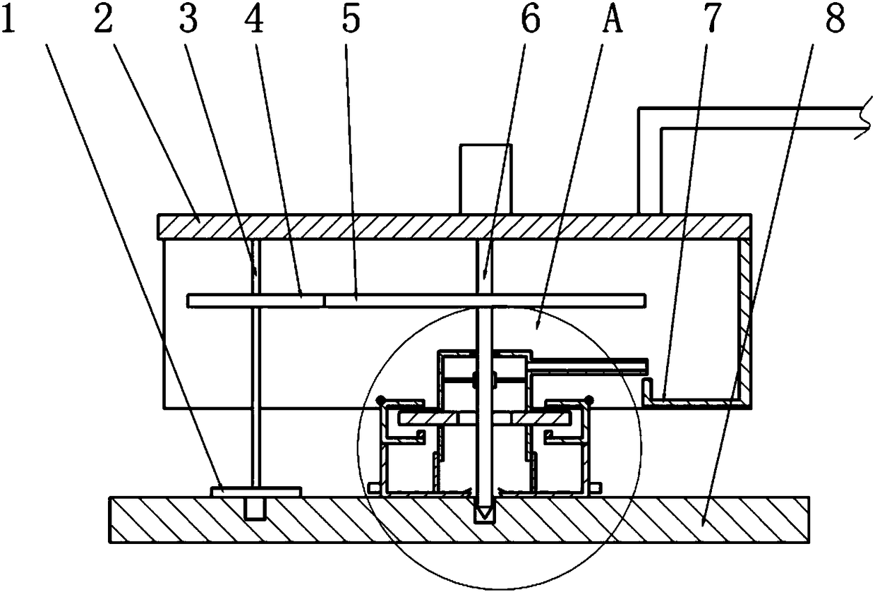
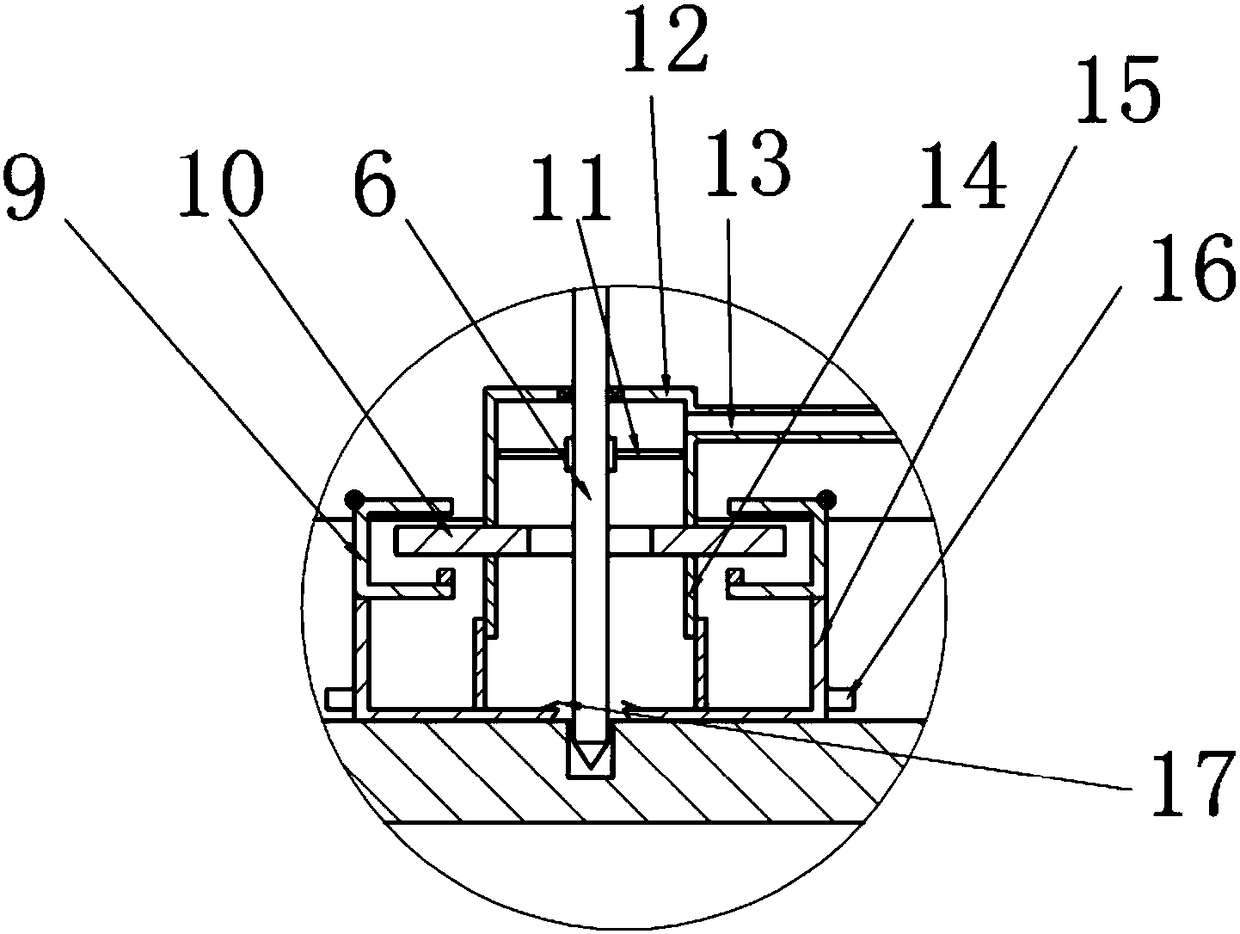
[0026] Example: such as figure 1 and figure 2 As shown, the drilling machine used in this embodiment includes a frame 2 on which a motor-driven drill 6 is rotatably connected. A cylindrical chip suction cover 12 is rotatably connected to the drill bit 6 , and the chip suction cover 12 is fixedly connected to the frame 2 . The bottom of the dust suction cover 12 is fixedly connected with a fixed plate 10, and the bottom of the fixed plate 10 is fixedly connected with a telescopic cover 14 that can be stretched up and down. The fixed plate 10 is provided with a through hole, and the drill bit 6 passes through the through hole and the telescopic sleeve in sequence.

[0027] The two sides of fixed plate 10 are provided with rotatable clamping block 9, and clamping block 9 has opening, and fixed plate 10 both sides are positioned at opening, and clamping block 9 is rotatably connected on the frame 2, and the bottom of clamping block 9 is fixedly connected with cross-sectional sh...


PUM


Abstract

The invention belongs to the field of lamp processing, and particularly discloses a hole lamp processing technology. According to a main scheme, drilling takes the place of punching in the prior art so as to avoid the unevenness of the surface of a lamp holder; in addition, a lifting plate, telescopic sleeve and scrap-suction cover in a drilling machine form relatively closed space, and drilling scraps generated during square-shaped drilling are thrown into other drilled led lamp holes; negative-pressure vanes, scrap-suction cover and scrap discharge pipe in the drilling machine uniformly recover the drilling scraps, thereby providing convenience for the recovery of the drilling scraps; counterweight, clamping block and lifting plate in the drilling machine achieve that negative pressure is generated for providing an air inlet interval during drilling, and a rack is lifted to reduce the interval for preventing the drilling scraps from falling.

Description

technical field [0001] The invention belongs to the field of lamp processing, and in particular relates to a processing technology of a cave lamp. Background technique [0002] With the maturity of LED technology, the hole lamps in the home decoration ceiling began to use LED hole lights. LED hole lights include a rear shell, a face shell, a light-transmitting cover, a power module and an LED chip, and the face shell is fixed at the bottom of the rear shell. , the light-transmitting surface cover is fixed in the middle of the surface shell, and the LED chip is fixed on the rear shell. The light emitted by the LED chip is irradiated through the light-transmitting surface cover, and the LED chip needs a power supply module to provide power for it. The LED chip and the lamp holder are processed with a plurality of lamp holes for installing LED lamps. In the prior art hole lamp processing technology, stamping is usually used to form the installation hole of the LED lamp. Due to...

Claims


Application Information

Patent Timeline
Patent Type & Authority Applications(China)
IPC IPC(8): B23P15/00F21K9/90F21Y115/10
Inventor 张才孟
Owner 道真自治县梦幻灯饰有限公司
Learn More