High-speed elevator tensioning device

A tensioning device, high-speed elevator technology, applied in transportation and packaging, springs/shock absorbers, elevators, etc., can solve the problems of excessive wire rope swing, affecting the normal operation of the speed limiter, and vibration of the tensioning device. Avoid excessive swing effects

Pending Publication Date: 2021-08-10
丹阳市华富机械有限公司
View PDF7 Cites 1 Cited by
  • Summary
  • Abstract
  • Description
  • Claims
  • Application Information

AI Technical Summary

Problems solved by technology

The existing tensioning device generally uses a counterweight to hang under the tensioning wheel, but due to the high-speed operation of the elevator, the tensioning device will vibrate in the vertical direction when the elevator is stopped in an emergency, and the wire rope will also appear Excessive swing in the horizontal direction will cause the problem of the clamping column of the entire tensioning device, thus affecting the normal operation of the speed limiter

Method used


Image

  • High-speed elevator tensioning device
  • High-speed elevator tensioning device
  • High-speed elevator tensioning device

Examples


Embodiment Construction

[0025] The present invention is further illustrated in conjunction with the accompanying drawings and specific embodiments.

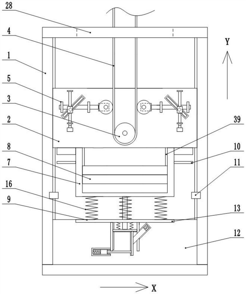
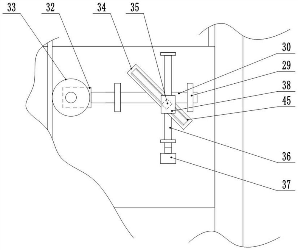
[0026] A high-speed elevator tensioning device, including a frame 1, a translational plate 2 that is moved within the outer frame 1, and is rotatably mounted on the translational plate 2 by the rolling bearing. 3, bypassing the tensioner 3 and tensioned Wheel 3 frictionally driven wire rope 4, wire rope 4 passes through the outer frame 1, mounted on the tension wheel 3 and is located on the pair of adjustment assembly 5 on the left and right tensioning wheel 3, and is mounted on the bottom of the translation plate 2 by the bolt. Box 7, movingly mounted a plurality of kings 8 on the inner frame 7, mounted on the shock absorbing assembly 9 at the bottom of the outer frame 1, and the inside of the inner frame 7 is mounted on both sides of the left and right side, and the outer frame 1 is left. A proximity switch 11 is installed on the side.

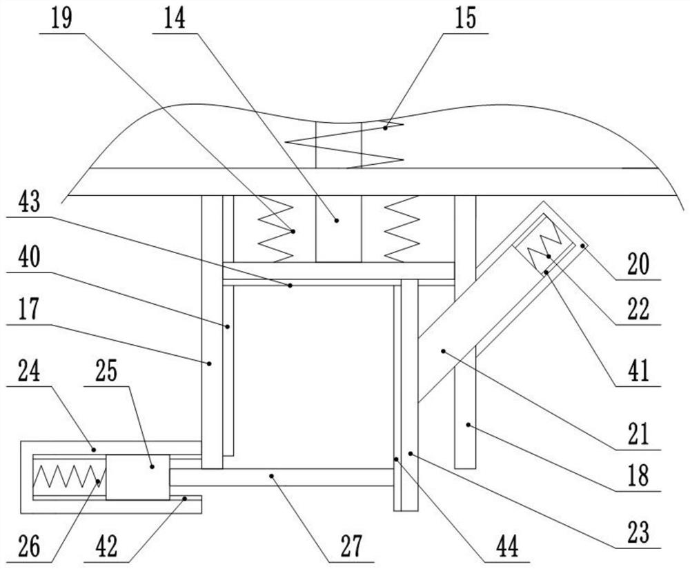
[0027] The dampin...


PUM


Abstract

The invention discloses a high-speed elevator tensioning device. According to the high-speed elevator tensioning device, the problem that a tensioning device vibrates in the vertical direction under the emergency braking working condition of an existing elevator is solved through a damping assembly. When the elevator is braked emergently, upward pulling and throwing force is generated on the tensioning device, a damping rod is driven to move through the pulling and throwing force, a buffer plate A, a buffer plate B and a buffer plate C move, a spring A, springs B, a spring C, a spring D and springs E deform, and impact energy generated during emergency braking is converted into kinetic energy and elastic potential energy. The problem that the tensioning device is clamped due to the fact that the swing amplitude of an existing steel wire rope in the horizontal direction is too large is solved through the adjusting assembly. An adjusting motor drives a driving rod to rotate, a driving ring moves in the central axis direction of the driving rod, an adjusting base moves in an adjusting frame while moving along with the driving ring, the adjusting rod is driven to move, and therefore the distance between an adjusting wheel and a steel wire rope is changed.

Description

Technical field [0001] The present invention relates generally to a high-speed elevator tensioning device. Background technique [0002] The elevator limiter is one of the safety control components in the elevator safety protection system. When the elevator is running in operation, it makes the car at speed, and even the danger of the fall, and all other safety protection devices do not work, the elevator limiter stops the elevator car. [0003] The limiter includes a speed limit device, a wire rope, a tensioning apparatus, and a speed limit device mounted on top of the elevator hole, and the tensioning device is mounted at the bottom of the elevator hole, the wire rope passes through the speed limit device of the speed limit device and the tensioning device. The tight line connects the speed limiter and tensioning wheels. The existing tensioning device generally uses a counterweight block to hang down the tensioning wheel, but due to the high speed of the elevator, the tensionin...

Claims


Application Information

Patent Timeline
Patent Type & Authority Applications(China)
IPC IPC(8): B66B7/06B66B5/04B66B5/06B66B17/12F16F15/00F16F15/067
CPCB66B7/06B66B5/044B66B5/06B66B17/12F16F15/002F16F15/067
Inventor 徐华南徐强周有发
Owner 丹阳市华富机械有限公司
Why Eureka
Try Eureka