Windproof safety self-reinforcing door

A technology of safety and reinforcement, applied in door/window accessories, wing parts, switches with brakes, etc., can solve the problem that the door body is easily closed or opened by the wind or even hits the door frame.

Inactive Publication Date: 2021-08-10
HUZHOU YUEBIN INTELLIGENT TECH CO LTD
View PDF0 Cites 0 Cited by
  • Summary
  • Abstract
  • Description
  • Claims
  • Application Information

AI Technical Summary

Problems solved by technology

[0004] The purpose of the present invention is to provide a windproof and safe self-reinforced door that prevents the wind from closing and reduces the collision of the door body in view of the problem that the door body is easily closed or opened by the wind or even hits the door frame

Method used


Image

  • Windproof safety self-reinforcing door
  • Windproof safety self-reinforcing door
  • Windproof safety self-reinforcing door

Examples


Embodiment 1

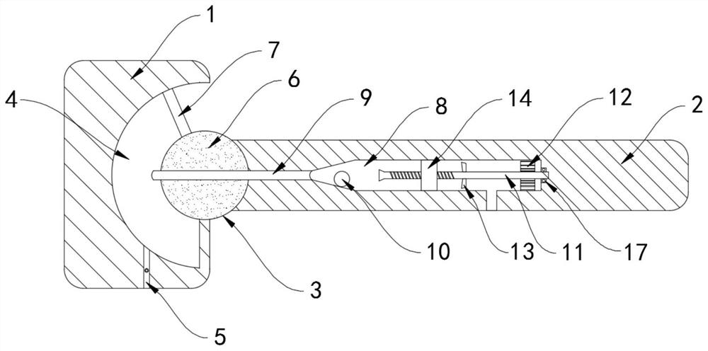
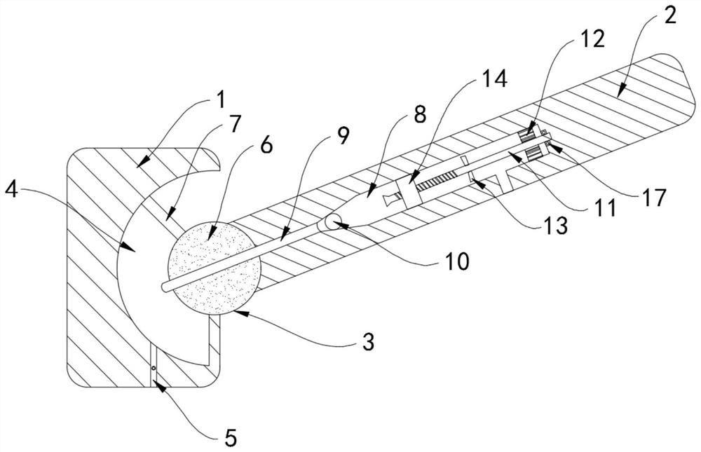
[0021] Such as Figure 1-3 As shown, a windproof safety self-reinforcing door includes a door frame 1 and a door body 2, the door frame 1 is fixedly installed in the wall, the door body 2 and the door frame 1 are hinged through hinges, and a self-reinforcing door frame is installed between the door frame 1 and the door body 2. Reinforcing member 3, self-reinforcing member 3 includes an arc-shaped cavity 4 arranged in the door frame 1, a one-way air intake hole 5 communicating with the outside world is provided on the side wall of the arc-shaped cavity 4, and the one-way air intake hole 5 only allows the outside world to The air enters the arc cavity 4, and the arc cavity 4 is rotatably connected with a vertical support shaft 6. The door body 2 is fixedly connected with the side wall of the support shaft 6, and a sealing plate 7 is fixedly installed on the side wall of the support shaft 6. , the sealing plate 7 is in sealing sliding connection with the side wall of the arc cavi...

Embodiment 2

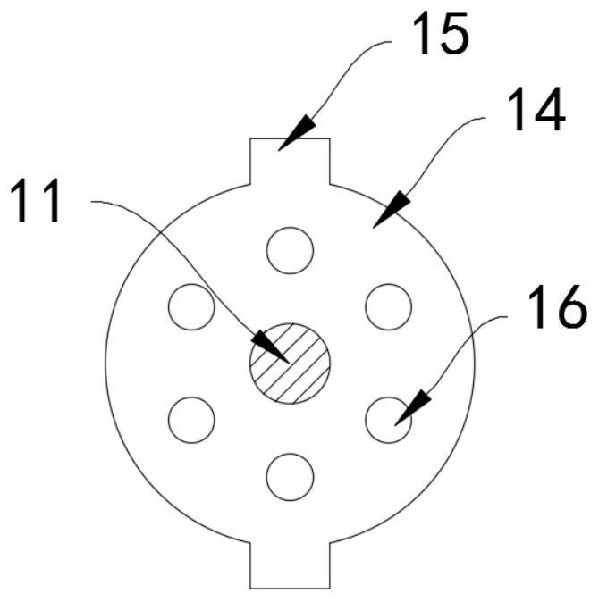
[0029] Such as Figure 4 As shown, the difference between this embodiment and Embodiment 1 is that the barrier ball 10 includes a spherical air bag 18 and a permanent magnet sheet 19 attached to the surface of the spherical air bag 18, the threaded sleeve 14 is made of magnetic material, and the permanent magnet sheet 19 The same poles repel each other with the threaded sleeve 14, and the air duct 9 is made of metal heat-conducting material.

[0030] In this embodiment, when the door body 2 is repeatedly closed and opened by the wind force, heat is generated by repeated rotation and friction between the support shaft 6 and the door frame 1, and the heat is conducted to the spherical air bag 18 through the air duct 9, shrinking and expanding due to heat. Due to the effect of cold shrinkage, the spherical airbag 18 expands, and the radius of the barrier ball 10 increases. The threaded sleeve 14 only needs to move a short distance to push the barrier ball 10 to completely seal th...


PUM


Abstract

The invention belongs to the field of building parts, and particularly relates to a windproof safety self-reinforcing door. The windproof safety self-reinforcing door comprises a door frame and a door body; the door frame is fixedly installed in a wall; the door body is hinged to the door frame through hinges; a self-reinforcing part is further installed between the door frame and the door body; the self-reinforcing part comprises an arc-shaped cavity formed in the door frame; a one-way air inlet communicated with the outside is formed in the side wall of the arc-shaped cavity; a vertically-arranged supporting shaft is rotationally connected into the arc-shaped cavity; the door body is fixedly connected with the side wall of the supporting shaft; a sealing plate is fixedly installed on the side wall of the supporting shaft, and the sealing plate is in sealed sliding connection with the side wall of the arc-shaped cavity; and an exhaust cavity communicated with the outside is formed in the door body, and one end of the exhaust cavity communicates with the arc-shaped cavity through an air guide pipe. Air in the air guide pipe can be prevented from flowing into the exhaust cavity through a blocking ball, so that the exhaust speed of the air in the arc-shaped cavity is greatly reduced, and the door body cannot be driven by airflow to strike the door frame suddenly to cause damage.

Description

technical field [0001] The invention belongs to the field of building components, in particular to a windproof safety self-reinforcing door. Background technique [0002] Doors and windows are the main ventilation channels in house design. In daily life, it is often necessary to open the door for ventilation to keep the indoor air fresh. If there is a strong wind blowing to the door body, it will often drive the door body to open and close repeatedly, which not only affects indoor ventilation. , It will also emit a large collision sound, which will affect people's living and rest. When the wind is too strong, it will even push the door body to slam into the door frame, causing damage to the door body and unnecessary property loss. [0003] Therefore, we propose a windproof safety self-reinforcing door to solve the above problems. Contents of the invention [0004] The purpose of the present invention is to provide a windproof and safe self-reinforcing door that prevents w...

Claims


Application Information

Patent Timeline
Patent Type & Authority Applications(China)
IPC IPC(8): E05F5/02E05F5/06
CPCE05F5/02E05F5/06E05Y2900/132
Inventor 沈超锋
Owner HUZHOU YUEBIN INTELLIGENT TECH CO LTD
Why Eureka
Try Eureka