Plastic Foam Molding Equipment

A molding equipment and technology of plastic foam, applied in the field of plastic molding, can solve problems such as low energy utilization rate, and achieve the effect of lowering temperature and speeding up discharge

Active Publication Date: 2020-04-10
遵义锦鸿富科技发展有限公司
View PDF6 Cites 0 Cited by
  • Summary
  • Abstract
  • Description
  • Claims
  • Application Information

AI Technical Summary

Problems solved by technology

When the device is molding plastic foam, because it uses water heating and pressurization, a large amount of high-heat and high-pressure water vapor will be formed during the molding process; after the plastic foam molding is completed, both water vapor and hot water will be discharged directly, making the low energy efficiency

Method used


Image

  • Plastic Foam Molding Equipment
  • Plastic Foam Molding Equipment
  • Plastic Foam Molding Equipment

Examples


Embodiment Construction

[0023] The present invention will be described in further detail below by means of specific embodiments:

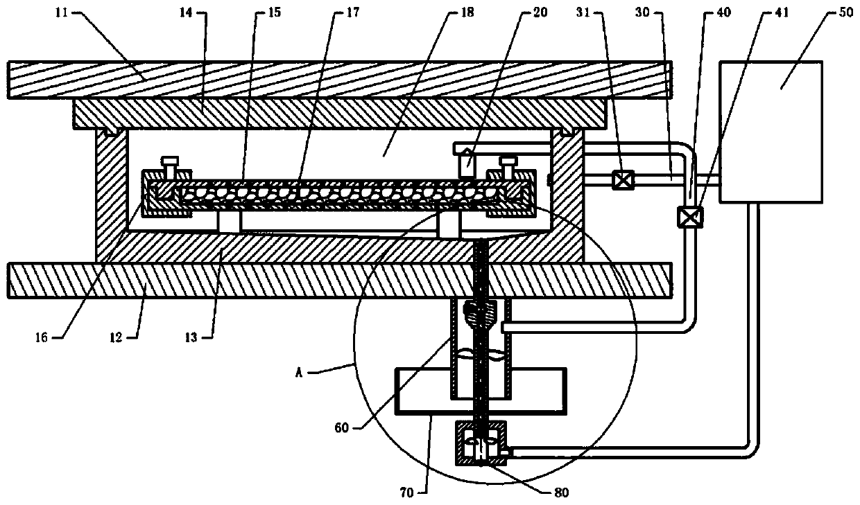
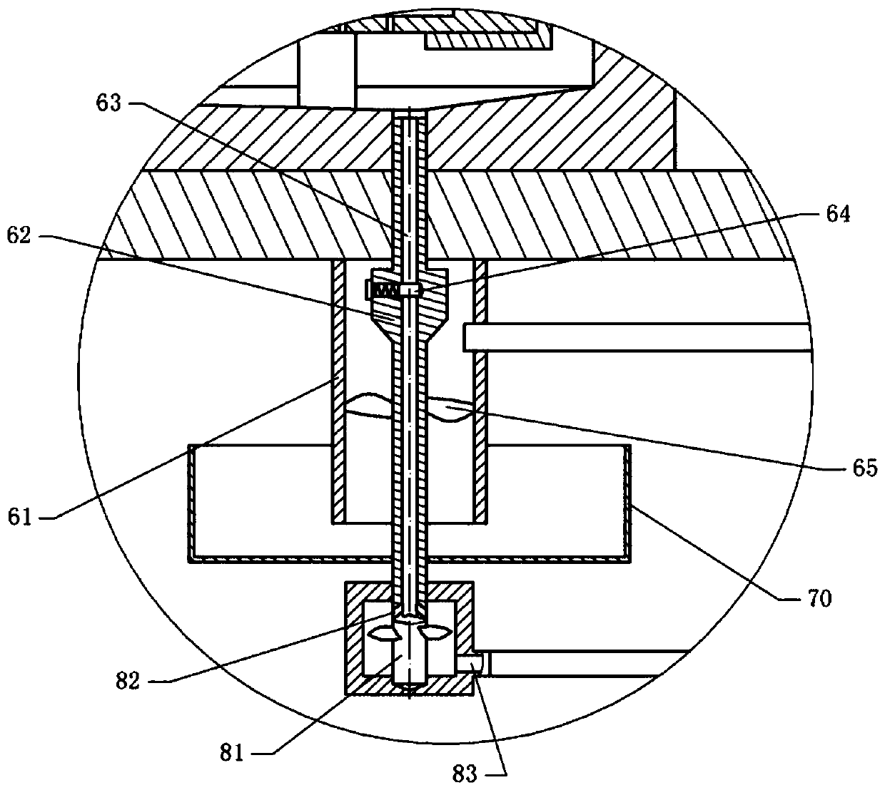
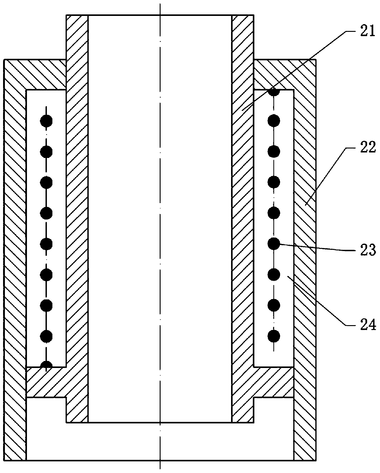
[0024] The reference signs in the accompanying drawings of the description include: upper hot pressing plate 11, lower hot pressing plate 12, water tank 13, cover plate 14, upper mold pressing plate 15, buckle 16, lower mold pressing groove 17, steam generator 18, Telescopic tube 20, inner tube 21, outer tube 22, extension spring 23, medium chamber 24, water inlet pipe 30, second stop valve 31, exhaust pipe 40, first stop valve 41, hot water tank 50, turbine mechanism 60, Pipe body 61, rotating shaft 62, guide channel 63, blocking block 64, turbine 65, cold water tank 70, pump body 80, input shaft 81, water inlet 82, water outlet 83.

[0025] The embodiment is basically as figure 1 , figure 2 and image 3 Shown:

[0026] The plastic foam molding equipment of the present embodiment comprises a two-layer hot press machine provided with an upper hot press plate 11 and a...


PUM

PropertyMeasurementUnit
boiling pointaaaaaaaaaa

Abstract

The invention relates to the field of plastic molding, and in particular, relates to a plastic foam forming device which mainly comprises an upper hot-pressing plate, a lower hot-pressing plate, a forming mechanism and a cooling device; the cooling device includes an exhaust pipe connected to the upper part of a steam generator, a turbine mechanism connected to the exhaust pipe, a pump body connected to the turbine mechanism, and a hot water tank connected with a pump body; the turbine mechanism comprises a tube body and a turbine, the turbine is rotatingly connected with the tube body througha rotating shaft, and one end of the tube body communicates with the exhaust pipe; the pump body comprises a water inlet, a water outlet and an input shaft; the rotating shaft of the turbine mechanism is fixed with the input shaft; the rotating shaft is internally provided with a diversion channel, one end of the diversion channel communicates with the steam generator, and the other end of the diversion channel communicates with the water inlet of the pump body; the rotating shaft is provided with a plugging block sliding along the radial direction of the rotating shaft; the diversion channelis conducted when the rotating shaft rotates; the water outlet of the pump body communicates with the hot water tank, and a first stop valve is arranged on the exhaust pipe. The device improves the energy utilization rate and accelerates the cooling rate.

Description

technical field [0001] The invention relates to the field of plastic molding, in particular to a plastic foam molding equipment. Background technique [0002] Plastic foam, also known as foam plastic, is a kind of polymer material formed by a large number of gas micropores dispersed in solid plastic. It has the characteristics of light weight, heat insulation, sound absorption, shock absorption, etc., and its dielectric properties are better than those of matrix resin. , is very versatile. The preparation process of plastic foam generally includes: ① introducing gas into liquid or molten plastic to generate micropores; ② increasing the micropores to a certain volume; ③ fixing the micropore structure by physical or chemical methods to obtain plastic foam. Plastic foam products include finished products made of plastic foam or finished products made of plastic as raw materials through foaming treatment. The shapes are diverse, and plastic foam products of various shapes can b...

Claims


Application Information

Patent Timeline
Patent Type & Authority Patents(China)
IPC IPC(8): B29C44/02B29C44/34
CPCB29C44/02B29C44/343
Inventor 申天玖
Owner 遵义锦鸿富科技发展有限公司
Why Eureka
Try Eureka