Supercharge Your Innovation With Domain-Expert AI Agents!

Anchor rod supporting structure with pressure relief function

A bolt support and functional technology, applied in the installation of bolts, mining equipment, earthwork drilling and mining, etc., can solve the problems of manpower, material resources, financial resources, time waste, roadway scrapping, failure to set up, etc., and achieve good support effect , simple operation, and the effect of increasing the budget

Inactive Publication Date: 2021-08-10
ANHUI UNIV OF SCI & TECH
View PDF0 Cites 0 Cited by
  • Summary
  • Abstract
  • Description
  • Claims
  • Application Information

AI Technical Summary

Problems solved by technology

However, since this bolt support has already been carried out, its position is set when the support is carried out, or even cannot be set, so it is likely to cause this part of the roadway to be scrapped directly, resulting in a large waste of manpower, material resources, financial resources and time.

Method used


Image

  • Anchor rod supporting structure with pressure relief function
  • Anchor rod supporting structure with pressure relief function
  • Anchor rod supporting structure with pressure relief function

Examples


Embodiment Construction

[0028] The following will clearly and completely describe the technical solutions in the embodiments of the present invention with reference to the drawings in the embodiments of the present invention.

[0029] In describing the present invention, it should be understood that the terms "upper", "lower", "front", "rear", "left", "right", "top", "bottom", "inner", " The orientation or positional relationship indicated by "outside", etc. is based on the orientation or positional relationship shown in the drawings, and is only for the convenience of describing the present invention and simplifying the description, rather than indicating or implying that the referred device or element must have a specific orientation, so as to Specific orientation configurations and operations, therefore, are not to be construed as limitations on the invention.

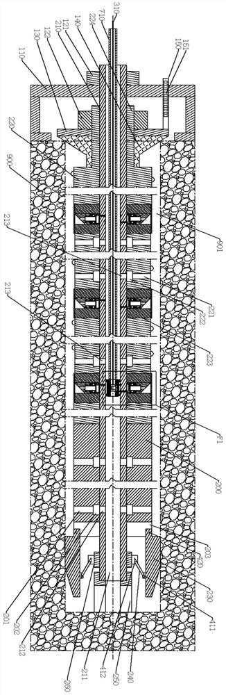
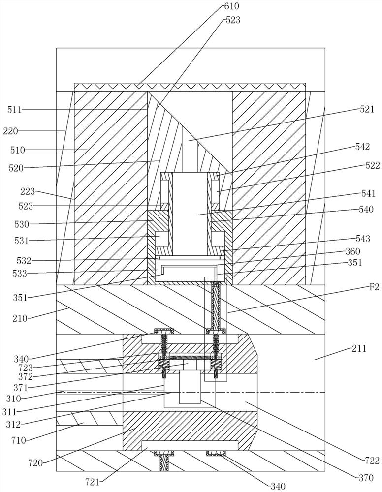
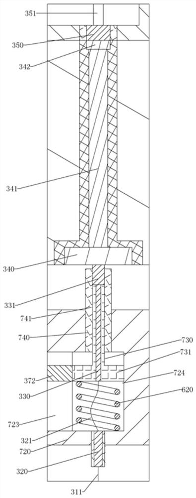
[0030] see Figure 1-3 , the bolt support structure of this embodiment includes an inner rod 210, an outer rod 220, and a sliding sleeve...


PUM


Abstract

The invention relates to an anchor rod supporting structure with a pressure relief function. The anchor rod supporting structure with the pressure relief function comprises an inner rod and an outer rod. The inner rod is sleeved with the outer rod in a circumferential rotation mode, one end of the inner rod penetrates out of the outer rod and penetrates through a base plate so as to be assembled with a first nut in a screwed mode through threads, and the base plate is pressed on the inner wall of a roadway, so that the inner rod is relatively fixed in the axial direction; an inserting groove is further formed in the outer rod, a gunpowder box is installed in the inserting groove, the interior of the gunpowder box is hollow and is divided into a sliding hole part and a gunpowder cavity through a limiting ring, and the gunpowder cavity is filled with gunpowder; a sliding hole part is clamped with a second sliding cylinder ring at one end of a sliding cylinder and can be assembled in an axial sliding manner, the other end of the sliding cylinder is arranged in a clamping block hole, clamped with a first sliding cylinder ring and can be assembled in an axial sliding manner, and the clamping block hole is formed in a clamping block; and an air injection hole is formed in the clamping block, one end of the air injection hole is communicated with the clamping block hole and a sliding cylinder hole in the inner side of the sliding cylinder, and the other end of the air injection hole penetrates through the clamping block. According to the anchor rod supporting structure with the pressure relief function provided by the invention, stretching and retracting are achieved in the mode that the outer rod and the inner rod are assembled in a sliding mode, so that the supporting stress can be adjusted by stretching and retracting the inner rod.

Description

technical field [0001] The invention relates to bolt support technology, in particular to a bolt support structure with pressure relief function. Background technique [0002] The bolt is the most basic part of roadway support in contemporary coal mines. It reinforces the surrounding rock of the roadway so that the surrounding rock can support itself. At present, the grouting bolt is the most common bolt in the mine. It is injected into the anchor hole through the grout, so that the grout solidifies the bolt and the surrounding surrounding rock into one to play the role of support. [0003] In the geological environment of some crushed stone, sandstone, and soft rock, the internal gaps are small. At this time, the method of grouting the anchor hole through the grouted anchor rod will make the diffusion range of the grout around the anchor hole small, that is, the anchor hole. The solidification range of the rods to the surrounding rock and soil is small, and the supporting ...

Claims


Application Information

Patent Timeline
Patent Type & Authority Applications(China)
IPC IPC(8): E21D20/00E21D20/02E21D21/00
CPCE21D20/003E21D20/02E21D21/0026
Inventor 娄培杰陈孝柱
Owner ANHUI UNIV OF SCI & TECH
Features
  • R&D
  • Intellectual Property
  • Life Sciences
  • Materials
  • Tech Scout
  • Unparalleled Data Quality
  • Higher Quality Content
  • 60% Fewer Hallucinations
Learn More