Medical environment logistics support monitoring system

A monitoring system and logistics technology, applied in services, measuring devices, instruments, etc. based on a specific environment, can solve the problem of inability to verify the cleanliness standard, and achieve the effect of convenient real-time transmission

Active Publication Date: 2021-09-07
SINODEU MEDICAL CO LTD
View PDF13 Cites 0 Cited by
  • Summary
  • Abstract
  • Description
  • Claims
  • Application Information

AI Technical Summary

Problems solved by technology

[0003] The cleanliness of the air in the operating room needs to be checked frequently. At present, whether the cleanliness of the operating room in the hospital is up to standard depends only on a petri dish test in an unmanned environment when the project is completed, but it is impossible to check whether the cleanliness is still up to standard after the hospital is put into use.

Method used


Image

  • Medical environment logistics support monitoring system
  • Medical environment logistics support monitoring system
  • Medical environment logistics support monitoring system

Examples


Embodiment 1

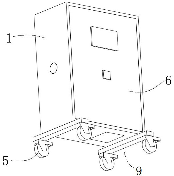
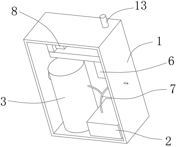
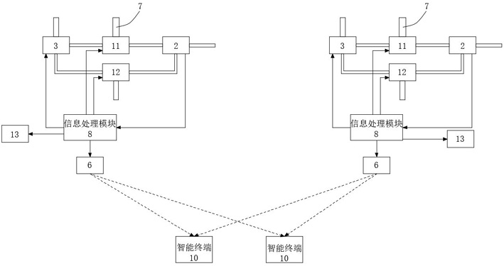
[0031] Embodiment 1: A medical environment logistics support monitoring system, including at least one detection device and at least one intelligent terminal 10 communicatively connected with the detection device, the detection device includes a housing 1, a particle counter 2 and an air filter 3 , the bottom surface of the housing 1 with the air inlet and the air outlet is provided with at least three universal wheels 5, the particle counter 2 communicated with the air outlet and the air filter 3 communicated with the air inlet are located in the housing 1 Inside;

[0032] A gas pipe 7 that runs through the housing 1 is connected to the air inlet of a first electromagnetic valve 11, and the two air outlets of the first electromagnetic valve 11 pass through the first pipeline, the second pipeline, the particle counter 2, and the air filter respectively. The air filter 3 is connected to the air inlet of a second solenoid valve 12 through a third pipeline, and the two air outlet...

Embodiment 2

[0045] Embodiment 2: A medical environment logistics support monitoring system, including 2 detection devices and 2 intelligent terminals 10 communicating with the detection devices, the detection device includes a housing 1, a particle counter 2 and an air filter 3. The bottom surface of the housing 1 with the air inlet and the air outlet is provided with at least 3 universal wheels 5, the particle counter 2 communicating with the air outlet and the air filter 3 communicating with the air inlet are located in the housing within 1;

[0046] A gas pipe 7 that runs through the housing 1 is connected to the air inlet of a first electromagnetic valve 11, and the two air outlets of the first electromagnetic valve 11 pass through the first pipeline, the second pipeline, the particle counter 2, and the air filter respectively. The air filter 3 is connected to the air inlet of a second solenoid valve 12 through a third pipeline, and the two air outlets of the second solenoid valve 12 ...


PUM


Abstract

The invention discloses a medical environment logistics support monitoring system, which includes at least one detection device and at least one intelligent terminal communicating with the detection device. The gas pipe of the first electromagnetic valve is connected to the air inlet of a first electromagnetic valve, and the two air outlets of the first electromagnetic valve are respectively connected to the particle counter and the air filter through the first pipeline and the second pipeline, and the air filter is passed through The third pipeline is connected to the air inlet of a second solenoid valve, and the two air outlets of the second solenoid valve are respectively connected to the particle counter and the air outlet through the fourth pipeline and the fifth pipeline. The intelligent terminal is used for Receive, store and / or analyze particle content information. On the basis of realizing the flexible monitoring of the air quality in the clean area in the hospital, such as the operating room, the present invention facilitates timely replacement of air filter consumables, thereby ensuring that the air cleanliness in the area is kept within the required range for a long time.

Description

technical field [0001] The invention relates to the field of air detection, in particular to a medical environment logistics support monitoring system. Background technique [0002] The operating room is a place to provide surgery and rescue for patients, and it is an important technical department of the hospital. The operating room should be connected to the operating department, and should also be close to the blood bank, intensive care unit, anesthesia recovery room, etc., and do a good job in the management of the four channels of surgical incision infection, namely: the air in the operating room, the items needed for the operation, and the care of doctors and nurses. Preventing infection of the fingers and the patient's skin is an important factor in ensuring the success of the operation. [0003] The cleanliness of the air in the operating room needs to be tested frequently. At present, whether the cleanliness of the operating room in the hospital is up to standard d...

Claims


Application Information

Patent Timeline
Patent Type & Authority Patents(China)
IPC IPC(8): G01N15/06G01N15/08H04W4/38G08B5/36
CPCG01N15/06G08B21/12G08B25/10G01N2015/0662
Inventor 黄梦楠冯平
Owner SINODEU MEDICAL CO LTD
Why Eureka
Try Eureka