
A magnetic circuit optimization method

An optimization method and magnetic circuit technology, applied in design optimization/simulation, CAD numerical modeling, etc., can solve time-consuming and labor-intensive problems, achieve optimal magnetization level, low current level, and speed up design time

Active Publication Date: 2022-07-26
UNIV OF ELECTRONICS SCI & TECH OF CHINA
View PDF5 Cites 0 Cited by
  • Summary
  • Abstract
  • Description
  • Claims
  • Application Information

AI Technical Summary

Problems solved by technology

[0003] The purpose of the present invention is to propose a magnetic circuit optimization method, which greatly reduces the workload of magnetic circuit optimization, and can achieve better optimal untie

Method used


Image

  • A magnetic circuit optimization method
  • A magnetic circuit optimization method
  • A magnetic circuit optimization method

Examples


Embodiment

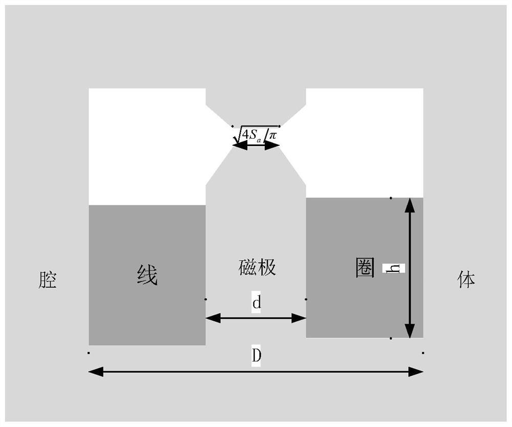
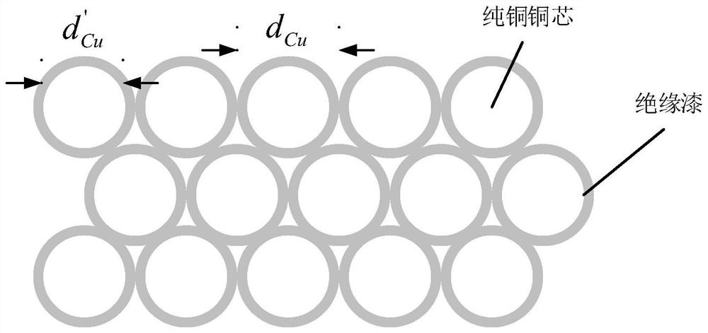
[0048] like figure 1 As shown, it is a schematic diagram of the magnetic circuit structure that needs to be optimized in the embodiment. The light-colored part is the cavity structure of the magnetic circuit, which is composed of soft magnetic materials, and its permeability is μ m (H a ); the dark part is the coil, which is made of copper wire with insulating paint. h min =0, h max =25,d min =10, d max =20, D min =0, D max =44, d' Cumin = 0.2, d' Cumax =0.5, P min =0, P max =18.


PUM


Abstract

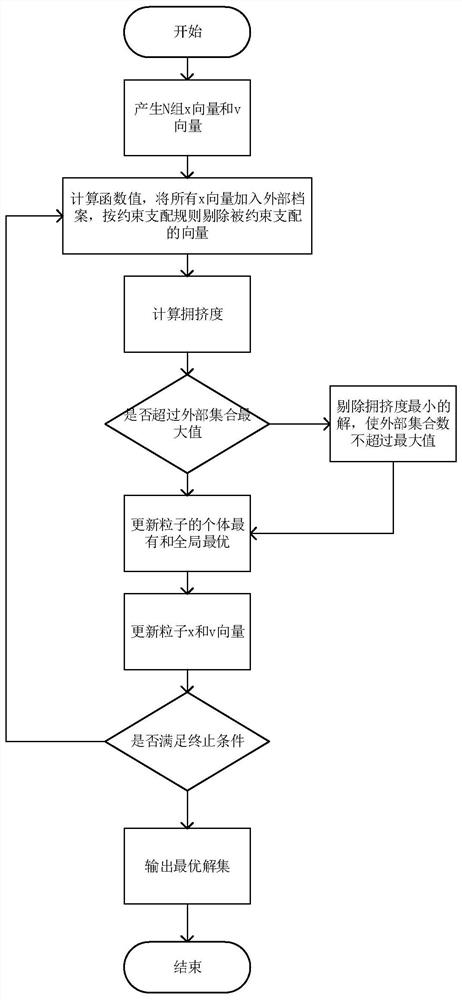
The invention provides a magnetic circuit optimization method, which belongs to the technical field of magnetic circuit design. The magnetic circuit optimization problem is established by mathematical modeling of the magnetic circuit, and the multi-objective particle swarm algorithm is used to solve the optimization problem, and the Pareto optimal solution set of the optimization problem is obtained. The optimal solution of the magnetic circuit. Compared with the traditional method, the present invention can select the non-dominated Pareto optimal solution, avoid blindly performing time-consuming and labor-intensive three-dimensional electromagnetic simulation, greatly speed up the design time of the magnetic circuit, and can achieve better magnetization level and lower current levels.

Description

technical field [0001] The invention belongs to the technical field of magnetic circuit design, and in particular relates to an optimization method of a magnetic circuit with a tunable magnetic field intensity. Background technique [0002] In electromagnets and microwave tunable magnetic devices, the design of soft magnetic circuits is involved. For example, microwave gyromagnetic materials will exhibit tensor permeability after applying a certain bias magnetic field. When electromagnetic waves act on microwave gyromagnetic materials, they will exhibit peculiar microwave characteristics due to the effect of tensor permeability. Since microwave gyromagnetic materials require a certain bias magnetic field to work properly, these devices all have bias magnetic circuits. This requires the design of the soft magnetic circuit to realize the application of the magnetic field. The traditional soft magnetic circuit design is to manually solve the magnetic circuit through the magne...

Claims


Application Information

Patent Timeline
Patent Type & Authority Patents(China)
IPC IPC(8): G06F30/25G06F111/10
CPCG06F30/25G06F2111/10
Inventor 杨青慧樊鑫安肖伟刘国超杜姗姗王明张怀武
Owner UNIV OF ELECTRONICS SCI & TECH OF CHINA
Learn More