An electrical control cabinet

A technology for electrical control cabinets and cabinets, which is applied in the directions of electrical components, substation/switch layout details, busbar/line layout, etc., which can solve the problem of reducing the neatness of connecting wire layout, low precision of reserved amount of connecting wires, insufficient energy conservation and environmental protection, etc. Problems, to achieve the effect of improving neatness and aesthetics, improving neatness and aesthetics, and improving stability

Active Publication Date: 2021-09-07
深圳市壹云智能科技有限公司
View PDF19 Cites 0 Cited by
  • Summary
  • Abstract
  • Description
  • Claims
  • Application Information

AI Technical Summary

Problems solved by technology

[0003] At present, the main factor affecting the neatness of the control cabinet is the layout of the connecting wires between the electrical components. Due to the large number of connecting wires, the layout is difficult, so the neatness of the connecting wire layout is reduced, which in turn affects the convenience of control cabinet maintenance. , Secondly, because the connection line needs a certain length of reserve for later maintenance and supplementation, this not only reduces the neatness of the connection line layout, but also because the reserved length of the connection line is generally controlled by the experience of the assembler , which directly leads to low accuracy of the reserved amount of connecting wires, which further reduces the neatness of connecting wire layout, and also causes waste of connecting wires, which is not energy-saving and environmentally friendly.
[0004] The existing measures to solve the above problems are to add wire slots in the control cabinet to centralize the connecting wires to a certain extent, but because of its simple structure, the finishing effect is mediocre, and there is no effective way to reserve the connecting wires. The processing method has gradually failed to meet the development requirements of the current society for excellence

Method used


Image

  • An electrical control cabinet
  • An electrical control cabinet
  • An electrical control cabinet

Examples


Embodiment Construction

[0029] The following will clearly and completely describe the technical solutions in the embodiments of the present invention with reference to the accompanying drawings in the embodiments of the present invention. Obviously, the described embodiments are only some, not all, embodiments of the present invention. Based on the embodiments of the present invention, all other embodiments obtained by persons of ordinary skill in the art without making creative efforts belong to the protection scope of the present invention.

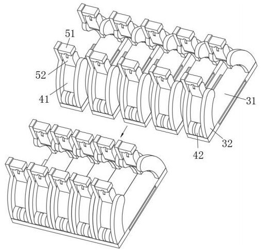
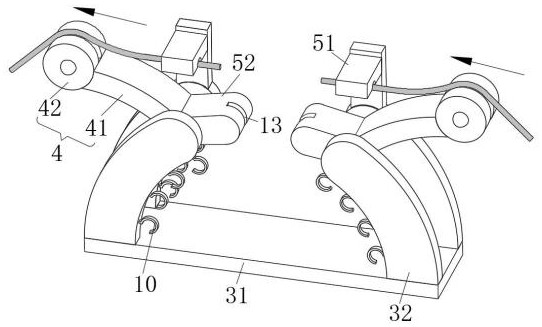
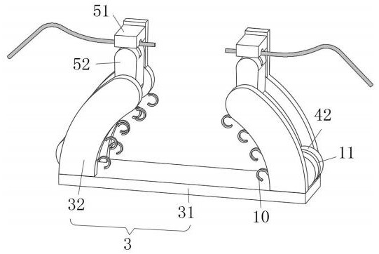
[0030] see Figure 1-7 : The electrical control cabinet includes a cabinet body 1, an installation part 2, an auxiliary connection part 3, a fixed plate 31, an arc frame 32, a path extension part 4, an arc plate 41, a cylindrical support block 42, and a force point transfer part 5. Guide piece 51, pressing piece 52, positioning assembly 6, damping shaft 61, limiting block 62, limiting assembly 7, buckle 71, card seat 72, connection assembly 8, connection assem...


PUM


Abstract

The invention provides an electrical control cabinet, which belongs to the technical field of electrical control, and includes a cabinet body. The cabinet body is provided with an assembly layout surface, and an auxiliary connection part is correspondingly provided on the assembly layout surface. The path extension part of the reserved amount of the connection line, the force point transfer part is connected between the path extension part and the auxiliary connection part, and the positioning component and the restriction component are connected between the auxiliary connection part and the path expansion part. The invention forms a rigid expansion route through the combination of the auxiliary connection part, the path expansion part, the force point transfer part, the positioning component and the limiting component, and precisely controls the reserved amount of the connecting line, effectively avoiding the problem of the connection line. Waste greatly improves the neatness and aesthetics of the wiring arrangement in the control cabinet, and correspondingly improves the neatness inside the control cabinet. At the same time, it has the advantages of good stability, energy saving, environmental protection and space saving.

Description

technical field [0001] The invention relates to the technical field of electrical control, in particular to an electrical control cabinet. Background technique [0002] The electrical control cabinet is to assemble and arrange the electrical components in the electrical cabinet through the auxiliary connecting parts according to the electrical wiring requirements, and is used to control and adjust the power and operation of the equipment. The assembly and arrangement of the electrical components in it must meet In addition to the requirements for the normal operation of the control system, it also needs to meet the requirements for neat appearance and easy maintenance. [0003] At present, the main factor affecting the neatness of the control cabinet is the layout of the connecting wires between the electrical components. Due to the large number of connecting wires, the layout is difficult, so the neatness of the connecting wire layout is reduced, which in turn affects the c...

Claims


Application Information

Patent Timeline
Patent Type & Authority Patents(China)
IPC IPC(8): H02B1/32H02B1/20
CPCH02B1/202H02B1/32
Inventor 欧敏
Owner 深圳市壹云智能科技有限公司
Why Eureka
Try Eureka