
Cylindrical heater

A cylindrical heater and a cylindrical technology, applied in the direction of heating elements, heating element shapes, ohmic resistance heating, etc., can solve the problems of more manufacturing processes and low heating efficiency, and achieve the effect of easy installation and operation and high heating efficiency

Pending Publication Date: 2021-08-10
NIPPON MEKTRON LTD
View PDF7 Cites 0 Cited by
  • Summary
  • Abstract
  • Description
  • Claims
  • Application Information

AI Technical Summary

Problems solved by technology

However, these technologies also have disadvantages of low heating efficiency due to the large number of parts, which increases the number of manufacturing processes, and the presence of other parts between the heating object and the heating element.

Method used


Image

  • Cylindrical heater
  • Cylindrical heater
  • Cylindrical heater

Examples


Embodiment

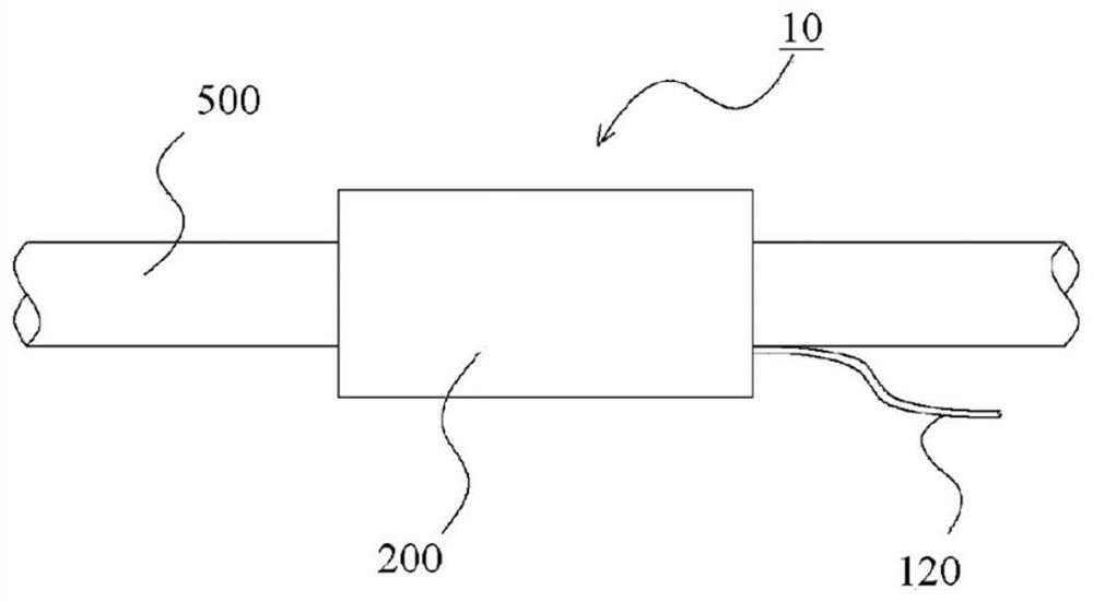
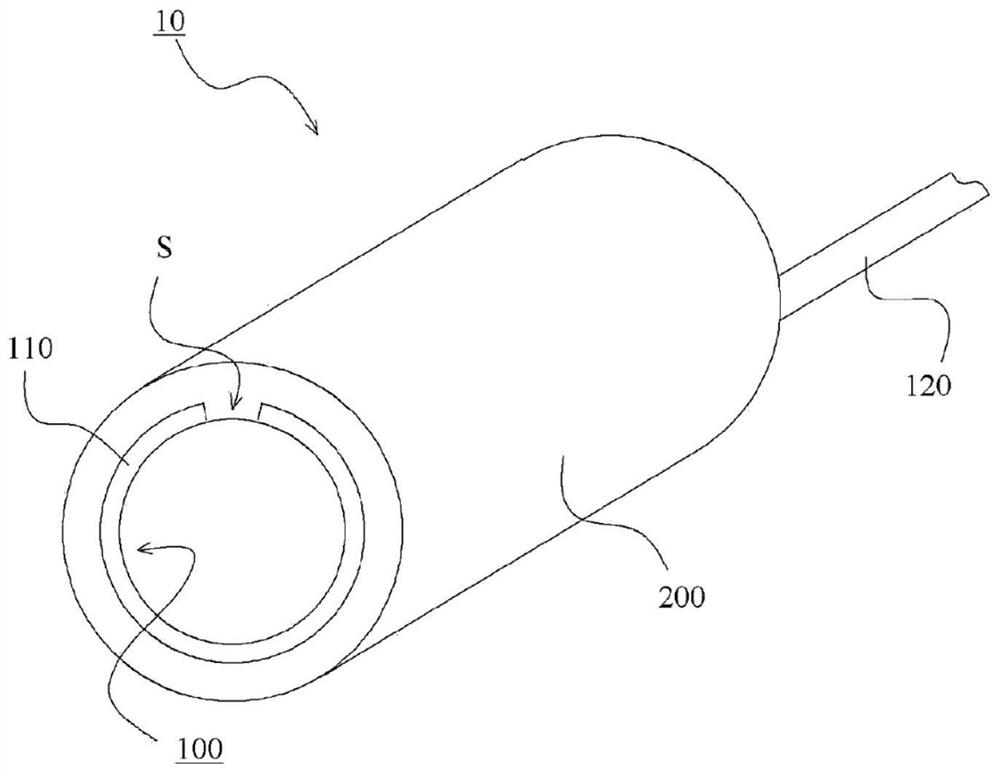
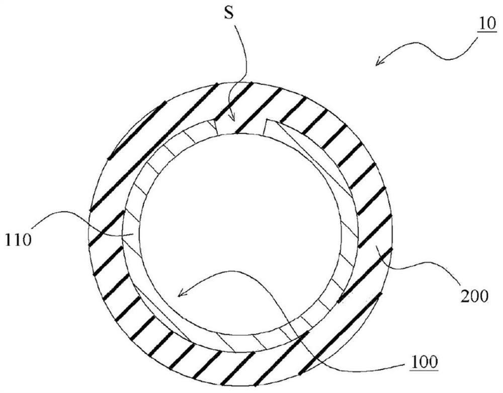
[0027] refer to Figure 1 to Figure 5 , the cartridge heater according to the embodiment of the present invention will be described. figure 1 It is an external view showing an example of use of the cartridge heater in the embodiment of the present invention, and shows the vicinity of the cartridge heater attached to the heating object. figure 2 is a perspective view of a cartridge heater in an embodiment of the present invention. image 3 is a schematic sectional view of a cartridge heater in an embodiment of the present invention. In addition, the cartridge heater in this embodiment is cylindrical, image 3 , shows a cross-sectional view of the cartridge heater taken along a plane perpendicular to the central axis of the cylinder. Figure 4 and Figure 5 It is a manufacturing process diagram of the cartridge heater in the Example of this invention.

[0028] (Examples of use of cartridge heaters)

[0029] like figure 1 As shown, the cartridge heater 10 in this embodi...


PUM


Abstract

Provided is a cylindrical heater which is easy to install and which has high heating efficiency. The cylindrical heater is characterized by being provided with: a cylindrical elastic body part 200; and a flexible printed wiring board 100 that is provided integrally with the elastic body part 200 and that has formed therein a heating circuit, wherein a heating part 110 that has formed therein the heating circuit in the flexible printed wiring board 100, is provided to the elastic body part 200 so as to be positioned along the inner circumferential surface of the elastic body part 200, with both ends thereof being apart from each other with a spacing S therebetween in the circumferential direction, and so as to be exposed on the inner circumferential surface side.

Description

technical field [0001] The present invention relates to a cartridge heater having a flexible printed wiring board on which a heating circuit is formed. Background technique [0002] Conventionally, in order to heat a cylindrical member or a columnar member, a cylindrical heater provided so as to cover the outer peripheral surface of these members is known. refer to Figure 6 , the cartridge heater in the conventional example will be described. Figure 6 is a schematic sectional view of a conventional cartridge heater. [0003] The illustrated cartridge heater 700 includes a double-sided tape 710 , a flexible printed wiring board 720 attached to the double-sided tape 710 , and a holding member 730 for holding the flexible printed wiring board 720 . A heating circuit is formed on the flexible printed wiring board 720 and has a function of generating heat by applying a voltage. In addition, the holding member 730 is formed of a cylindrical member. [0004] The procedure for ...

Claims


Application Information

Patent Timeline
Patent Type & Authority Applications(China)
IPC IPC(8): H05B3/06H05B3/54
CPCH05K1/0212H05K1/167H05K1/0393H05K2201/056H05B3/58H05B3/34H05B2203/003H05B3/06H05B3/54H05K1/147
Inventor 林达郎关庄太岩城宏和佐佐木崇
Owner NIPPON MEKTRON LTD
Learn More