Centrifugal gas dehumidification device

A centrifugal, gas technology, used in gas treatment, separation methods, dispersed particle separation, etc., can solve the problems of high energy consumption and low air dehumidification efficiency, and achieve low energy consumption, easy miniaturization and huge manufacturing needs , Efficient dehumidification effect

Pending Publication Date: 2021-08-13
KUNMING UNIV OF SCI & TECH
View PDF11 Cites 0 Cited by
  • Summary
  • Abstract
  • Description
  • Claims
  • Application Information

AI Technical Summary

Problems solved by technology

[0003] The main purpose of the present invention is to provide a centrifugal gas dehumidification device, which is based on the theory of visc

Method used


Image

  • Centrifugal gas dehumidification device
  • Centrifugal gas dehumidification device
  • Centrifugal gas dehumidification device

Examples


Embodiment 1

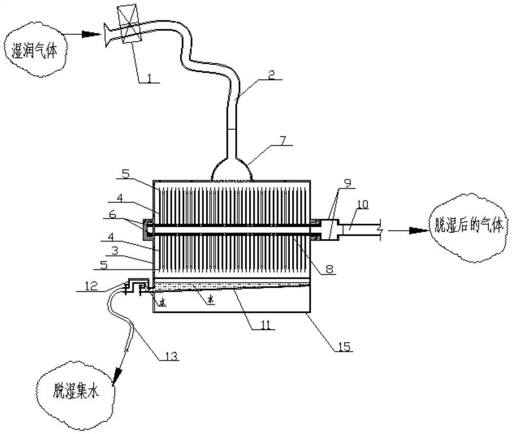
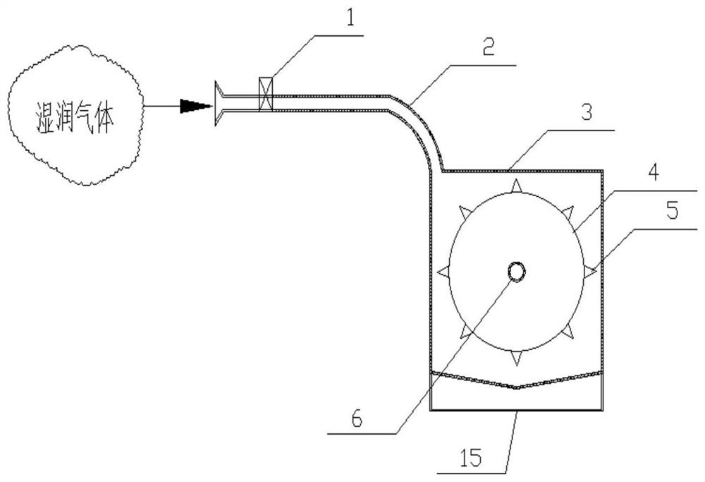
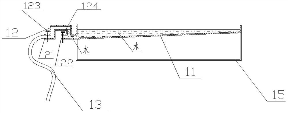
[0029] Embodiment 1: as Figure 1-4 As shown, a centrifugal gas dehumidification device includes an air pump 1, an air guide tube 2, a sealed box 3, a light hard disc 4, a water collecting tip 5, a hollow rotating shaft 6, an expanded air inlet 7, a communication hole 8, Air outlet 9, air outlet conduit 10, sink 11, water outlet 12, water guide pipe 13;

[0030] The air pump 1 is used to pump the gas to be dehumidified in the environment into the dehumidification device. The air pump 1 is connected to the inlet end of the air guide tube 2, and the outlet end of the air guide tube 2 is connected to the expansion air inlet 7, and the expansion air inlet 7 It is connected with the middle part of the top of the sealing box 3, and the inner cavity of the sealing box 3 is provided with a hollow rotating shaft 6 horizontally. Disc 4, the top of each said lightweight hard disc 4 is provided with some water collecting tips 5, and several communication holes 8 are arranged between two ...


PUM


Abstract

The invention discloses a centrifugal gas dehumidification device. The centrifugal gas dehumidification device comprises a gas pump, a gas guide pipe and the like, wherein the gas pump is connected with the gas inlet end of the gas guide pipe; the gas outlet end of the gas guide pipe is connected with an expansion gas inlet; the expansion gas inlet is connected with the middle of the top end of a sealing box; a hollow rotating shaft is transversely arranged in an inner cavity of the sealing box; a plurality of light hard wafers are evenly arranged on the hollow rotating shaft; a plurality of water gathering tips are arranged at the top end of each light hard wafer; a plurality of communicating holes are formed between every two adjacent light hard wafers; one end of the hollow rotating shaft is sealed, and the other end of the hollow rotating shaft communicates with one end of a gas outlet; the other end of the gas outlet is connected with a gas outlet guide pipe; a water collecting groove is formed in the bottom of the sealing box; and a water outlet part is arranged at the outlet end of the water collecting groove. According to the invention, the technical problems of low efficiency and high energy consumption in an air dehumidification process are solved.

Description

technical field [0001] The invention relates to a centrifugal gas dehumidification device, belonging to the field of gas dehumidification. Background technique [0002] Gas is widely used in industrial production, but the moisture contained in it must be removed before use. At present, most gas dehumidification methods use chemical dehumidification or membrane separation technology for dehumidification. Chemical dehumidification is relatively slow. High and costly; while there are many types of gas dehumidification devices, there are currently few gas dehumidification devices that can efficiently dehumidify wet gas and have low energy consumption. In view of the above situation, for this reason, we propose a centrifugal gas dehumidification device. Contents of the invention [0003] The main purpose of the present invention is to provide a centrifugal gas dehumidification device, which is based on the theory of viscous force and gravity, and aims to effectively solve the ...

Claims


Application Information

Patent Timeline
IPC IPC(8): B01D53/26B01D53/24
CPCB01D53/26B01D53/24B01D2258/02
Inventor 黄永辉毛泽凌杨鸿雁陈文梦张智宇
Owner KUNMING UNIV OF SCI & TECH
Why Eureka
Try Eureka