
Intelligent forging equipment and forging method thereof

A kind of equipment and intelligent technology, which is applied in the direction of metal processing equipment, manufacturing tools, forging/pressing/hammer devices, etc., can solve the problems of reducing the labor intensity of the staff, time-consuming and labor-intensive forging parts, and unfavorable problems, so as to reduce labor costs and achieve good results. Application prospects and the effect of improving work efficiency

Pending Publication Date: 2021-08-13
陈安琪
View PDF8 Cites 2 Cited by
  • Summary
  • Abstract
  • Description
  • Claims
  • Application Information

AI Technical Summary

Problems solved by technology

[0004] In order to overcome the limitations of the existing forging equipment due to the structure, it is time-consuming and laborious to manually turn over the forged parts, which is not conducive to improving work efficiency and will increase the labor cost of the manufacturer. Inconvenient, not conducive to reducing the labor intensity of the staff, not conducive to the disadvantages of improving work efficiency, the present invention provides a forging equipment body based on the use of air hammer as the forging power, the forging parts can be fully intelligent, and the whole process does not require manual operation. It can automatically turn the front and back of the parts up and down for forging, thereby realizing an intelligent forging equipment and a forging method that brings convenience to the staff, improves work efficiency, and reduces the labor cost of the production side.

Method used


Image

  • Intelligent forging equipment and forging method thereof
  • Intelligent forging equipment and forging method thereof

Examples


Embodiment Construction

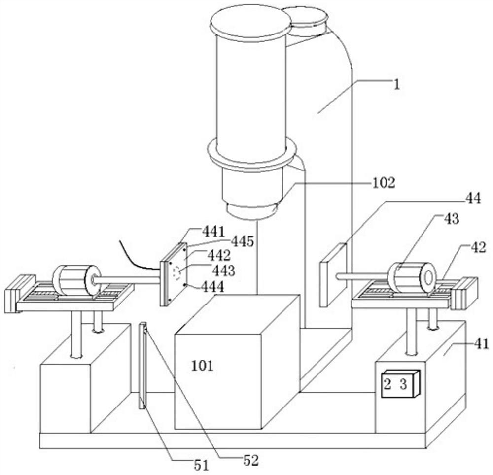
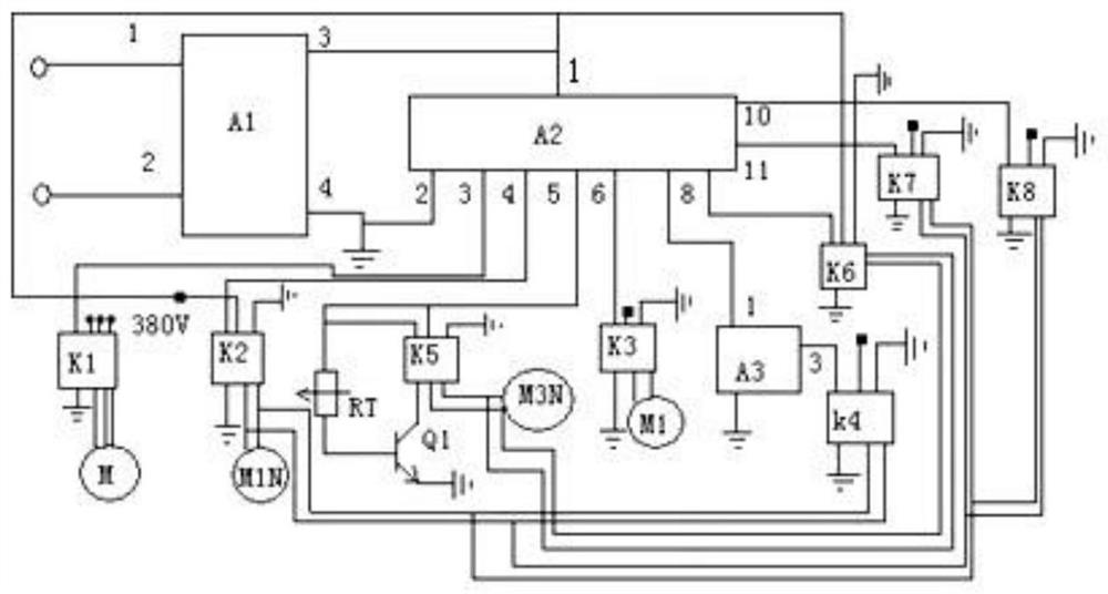
[0019] figure 1 , 2 As shown, an intelligent forging equipment includes a forging equipment body 1 using an air hammer as the forging power, a stabilized power supply 2; it also has a height detection mechanism, an overturning mechanism and a control circuit 3; there are two sets of the overturning mechanism, Each set of overturning mechanisms includes an electric push rod type lifting platform 41, an electric screw rod linear slide 42, a motor reduction mechanism 43 and a top plate 44; The screw nuts are installed on the upper ends of the two piston rods of the electric push rod lifting platform 41, the motor reduction mechanism 43 is installed horizontally on the upper end of the sliding block of the electric screw linear slide table 42 through the screw nuts, and the middle part of one side of the top plate 44 is installed through the screw nuts Before the power output shaft of the motor reduction mechanism 43; the lower ends of the housings of the electric push rod type l...


PUM


Abstract

The invention discloses an intelligent forging equipment. The intelligent forging equipment comprises a forging equipment body and a voltage-stabilized source, and is further provided with a height detection mechanism, turn-over mechanisms and a control circuit; the turn-over mechanisms comprise electric push rod type lifting platforms, electric lead screw linear sliding tables, motor speed reducing mechanisms and jacking plates, the lower ends of the electric lead screw linear sliding tables are arranged at the upper ends of the electric push rod type lifting platforms, the motor speed reducing mechanisms are arranged at the upper ends of sliding blocks of the electric lead screw linear sliding tables, the jacking plates are arranged in front of power output shafts of the motor speed reducing mechanisms, and the electric push rod type lifting platforms of the two turn-over mechanisms are arranged at the two side ends of a forging table; the height detection mechanism comprises a supporting frame and a photoelectric switch, the supporting frame is arranged on one side of the forging table, and the photoelectric switch is arranged at the upper end of the supporting frame; and the forging equipment body, the voltage-stabilized source, the height detection mechanism, the turn-over mechanisms and the control circuit are electrically connected. A forging method comprises six steps. The intelligent forging equipment brings convenience to workers, improves the working efficiency, and reduces the labor cost expenditure of a producer.

Description

technical field [0001] The invention relates to the technical field of mechanical processing equipment and application methods, in particular to an intelligent forging equipment and a forging method thereof. Background technique [0002] Forging equipment is a relatively common mechanism used in the field of mechanical processing. During work, air hammers are used as power to perform hot forging on heated parts that need to be forged. In the forging parts of forging equipment, in order to achieve a good forging effect, it is generally required to turn over the parts during forging (up and down, front and back) so that multiple sides can be forged to achieve better metal properties. [0003] In the prior art, one kind of turning over of parts in forging is to manually turn over the parts with jigs, etc., and another is to turn over the parts through electromechanical equipment jigs and the like. Turning over parts by manual clamping is time-consuming and laborious, which is ...

Claims


Application Information

Patent Timeline
Patent Type & Authority Applications(China)
IPC IPC(8): B21J13/12B21J7/46
CPCB21J13/12B21J7/46
Inventor 陈安琪
Owner 陈安琪
Learn More