
Bevel gear clamping fixture

A technology of helical gears and gears, which is applied in the field of helical gear clamping fixtures, can solve problems such as the difficulty of clamping gears, and achieve the effect of rapid positioning and cutting

Inactive Publication Date: 2021-08-13
HEBEI INSTITUTE OF ARCHITECTURE AND CIVIL ENGINEERING
View PDF0 Cites 0 Cited by
  • Summary
  • Abstract
  • Description
  • Claims
  • Application Information

AI Technical Summary

Problems solved by technology

But in the cutting process, because the teeth of the helical gear and the axis have a certain angle, it is a difficult problem to clamp the gear

Method used


Image

  • Bevel gear clamping fixture

Examples


Embodiment 1

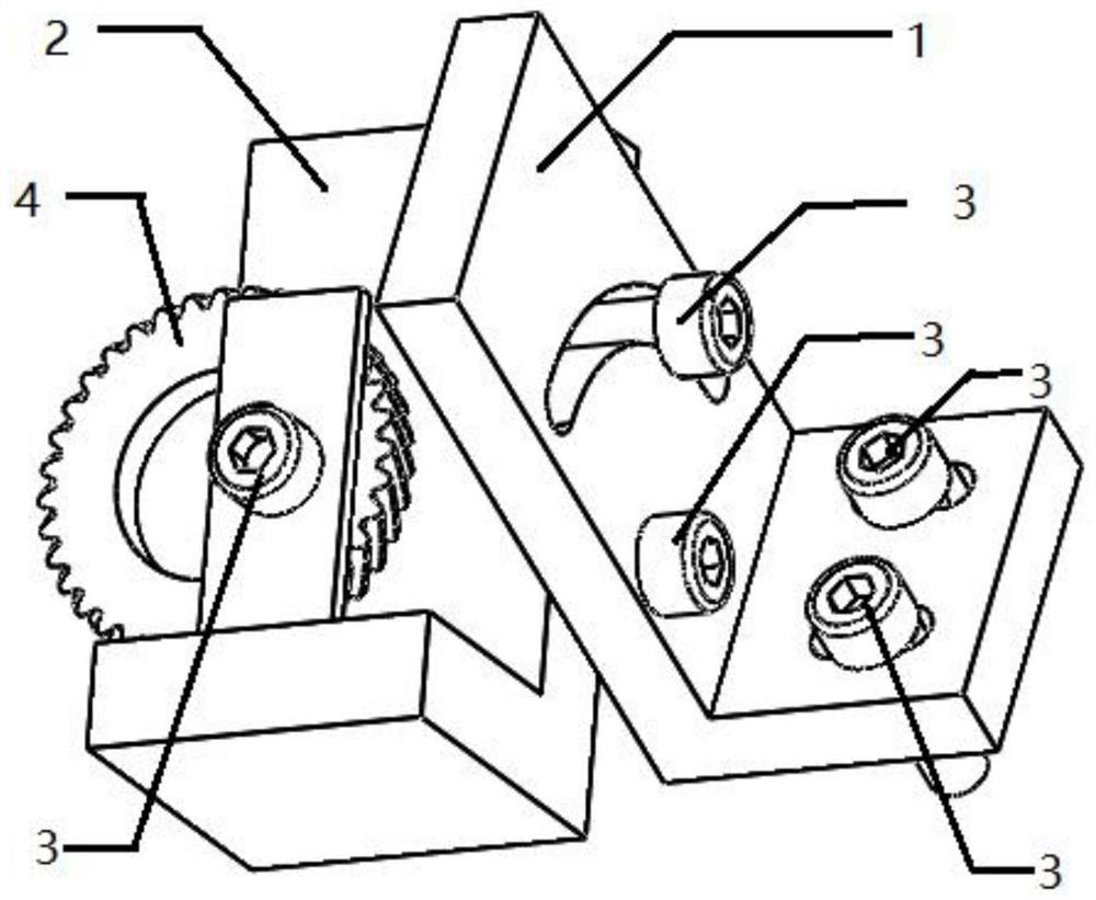
[0023] according to the above figure 1 As shown, a helical gear clamping fixture device is prepared, wherein the L-shaped iron 1 is installed on the wire cutting workbench to ensure verticality, the thickness is 12mm, the height is 100mm, and the base width is 50mm; the diameter of the through hole is 11mm, the center of the circle is 10mm from the side, and the distance The bottom edge is 32mm; the width of the fan-shaped groove on the main plane is 11mm, the center of the fixed through hole is the center, the radius is 20mm, and the arc length is 31mm, which is about 1 / 4 circle; the bottom surface of the L-shaped iron 1 is provided with two through holes with a diameter of 11mm, which are used for bolts The nut is connected with the wire cutting workbench; the L-shaped iron 2 is tightly connected with the L-shaped iron 1, with a thickness of 16mm, a height of 98mm, and a width of the bottom surface of 40mm. There is a through hole for the fixed connection of the helical gear....


PUM

PropertyMeasurementUnit
thicknessaaaaaaaaaa
heightaaaaaaaaaa
diameteraaaaaaaaaa

Abstract

The invention discloses a bevel gear clamping fixture. The mounting angle of a bevel gear can be adjusted, so that bevel teeth can be conveniently cut on electric spark wire cutting equipment. The fixture mainly comprises two pieces of L-shaped iron, one piece of the L-shaped iron is used for fixing the fixture on a workbench and is connected and fastened through bolts and nuts, a round hole and a fan-shaped round groove are formed in a vertical plane, the round hole is used for fixing the position of the L-shaped iron block for clamping a gear, and the fan-shaped groove is used for connecting and adjusting the clamping angle of the bevel gear. A round hole is formed in the other L-shaped iron and used for being connected with the position where the bevel gear is fastened, a rectangular gasket is additionally arranged at the connecting position, and clamping stability is guaranteed.

Description

technical field [0001] The proposal of the present invention is a jig that clamps a helical gear and can adjust the angle, and the helical gear can be clamped and cut on a wire cutting device by using the jig. Background technique [0002] Helical gears are commonly used and important workpieces in machine tools, automobiles, ships and other equipment. During use, gears need to withstand repeated shocks and vibrations, so to ensure performance, they need to have sufficient load-bearing capacity and strength. In order to measure the performance of the gear, it is cut into two parts along the tooth shape by wire cutting, and the section is professionally inspected to determine whether the gear meets the requirements. However, during the cutting process, since the teeth of the helical gear and the axis have a certain angle, it is a difficult problem to clamp the gear. In order to solve this problem, the present invention has developed and designed a set of fixtures, through w...

Claims


Application Information

Patent Timeline
Patent Type & Authority Applications(China)
IPC IPC(8): B23H7/02B23H11/00
CPCB23H7/02B23H11/003
Inventor 王新明吴东昊马晓欣冯小东康凯赫腾飞朱春华任玉灿陈立伟马宏闫小军郑永杰马海越张海东任志国
Owner HEBEI INSTITUTE OF ARCHITECTURE AND CIVIL ENGINEERING
Learn More