
A celery stick auxiliary cutting machine

A technology of cutting machine and lifting rod, which is applied in metal processing and other directions, can solve the problems of time-consuming and labor-intensive, inaccurate control of mouth opening, etc., and achieve the effect of reducing manual operation, facilitating cutting and fast collection

Active Publication Date: 2022-07-19
京之源(北京)农业有限公司
View PDF5 Cites 0 Cited by
  • Summary
  • Abstract
  • Description
  • Claims
  • Application Information

AI Technical Summary

Problems solved by technology

[0004] In order to overcome the shortcomings of the inability to precisely control the opening of the scissors during the use of the scissors, resulting in the use of ordinary scissors to cut off a lot of usable parts of celery, and the shortcomings of time-consuming and labor-intensive, technical problems to be solved : Provide an auxiliary cutting machine for celery stalks with precise cutting, time-saving and labor-saving

Method used


Image

  • A celery stick auxiliary cutting machine
  • A celery stick auxiliary cutting machine
  • A celery stick auxiliary cutting machine

Examples


Embodiment 1

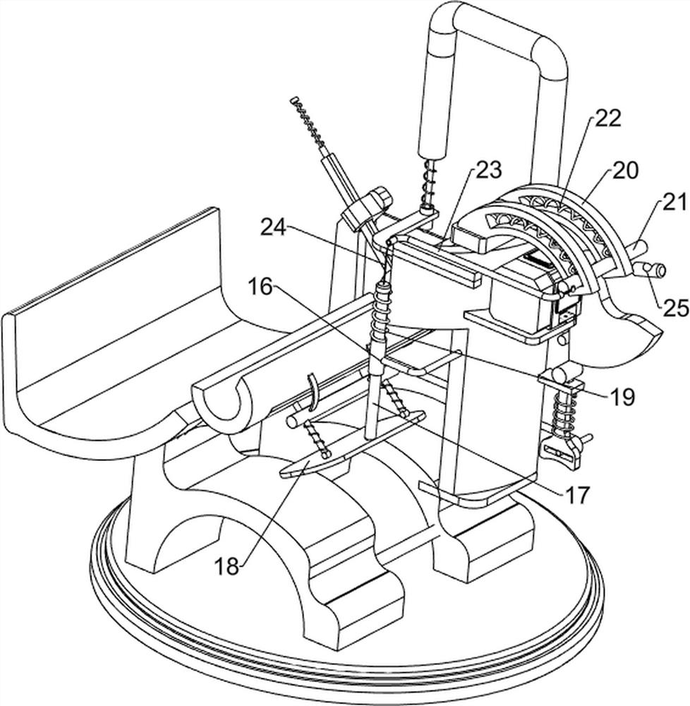
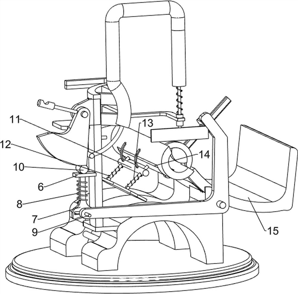
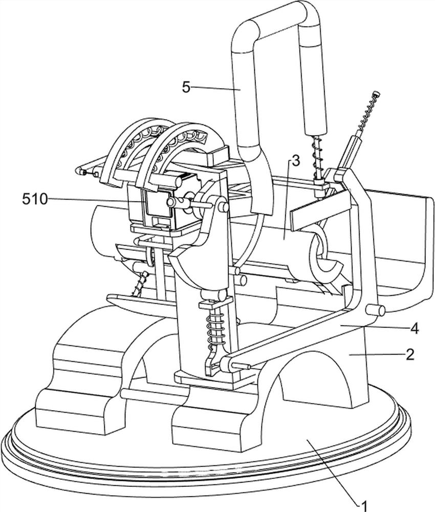
[0026] like figure 1 , figure 2 and image 3 As shown, a celery rod auxiliary cutting machine includes a base 1, a worktable 2, a placing table 3, a pressing mechanism 4 and a cutting mechanism 5. The top of the base 1 is symmetrically provided with a worktable 2, and the top of the worktable 2 is provided with There is a placing table 3 , a pressing mechanism 4 is arranged on the right side wall of the right working table 2 , and a cutting mechanism 5 is arranged on the front side wall of the right working table 2 .

[0027] The pressing mechanism 4 includes a fixed shaft 401, a folding frame 402, a mounting block 403, a fixed rod 404 and a pressing block 405. A fixed shaft 401 is provided on the right side wall of the right table 2, and the fixed shaft 401 is rotatably arranged There is a folding frame 402 , a mounting block 403 is provided on the upper end side wall of the folding frame 402 , a fixing rod 404 is fixed on the mounting block 403 , and a pressing block 405 ...

Embodiment 2

[0031] like Figure 4 , Figure 5 and Image 6As shown, on the basis of Embodiment 1, it also includes a guide block 6, a guide rod 7, a second elastic member 8, a first sliding shaft 9 and a top column 10. The lower part of the fixing frame 501 is provided with a guide block 6, which guides the A guide rod 7 is slidably arranged in the block 6, a character slot is formed at the bottom of the guide rod 7, a second elastic member 8 is connected between the guide rod 7 and the guide block 6, and the front end of the folding frame 402 is provided with a first sliding shaft 9 , the first sliding shaft 9 is slidingly matched with the slot of the guide rod 7, the top of the guide rod 7 is provided with a top column 10, the top column 10 is matched with the arc surface of the special-shaped top block 509, and the special-shaped top block 509 rotates counterclockwise. Push the top post 10 down.

[0032] The staff controls the servo motor 510 to drive the special-shaped top block 50...


PUM


Abstract

The invention relates to a cutting machine, in particular to an auxiliary cutting machine for celery sticks. The invention provides an auxiliary cutting machine for celery sticks which can cut accurately and save time and effort. The invention provides such an auxiliary cutting machine for celery sticks, which comprises: a base, a workbench is symmetrically arranged on the top of the base; a placement platform is provided with a placement platform on the top of the workbench; The cutting mechanism is provided on the side wall of the worktable. The celery is pressed by the pressing mechanism, and then the root of the celery is cut through the cooperation of the cutting mechanism. The device has a simple structure and is easy to operate.

Description

technical field [0001] The invention relates to a cutting machine, in particular to an auxiliary cutting machine for celery sticks. Background technique [0002] Celery is an indispensable condiment in everyday cooking. Usually, the roots of celery need to be processed after being bought back, so the roots need to be removed before further processing. [0003] At present, due to the large amount of celery that needs to be used in restaurants and hotels, scissors are usually used to cut off the roots of celery. However, due to the fact that the scissors cannot accurately control the opening of the mouth during use, when ordinary scissors are used to cut off the roots, a lot of usable parts of celery will be cut, and it is time-consuming and labor-intensive. Therefore, it is necessary to design a precise cutting method. , A time-saving and labor-saving celery stick auxiliary cutting machine to solve the above problems. SUMMARY OF THE INVENTION [0004] In order to overcom...

Claims


Application Information

Patent Timeline
Patent Type & Authority Patents(China)
IPC IPC(8): B26D1/08B26D7/02B26D7/32
CPCB26D1/08B26D7/02B26D7/32
Inventor 杨新生
Owner 京之源(北京)农业有限公司
Learn More